


Operating instructions
A3G350-BK06-G6
Translation of the original operating instructions
3. TECHNICAL DATA
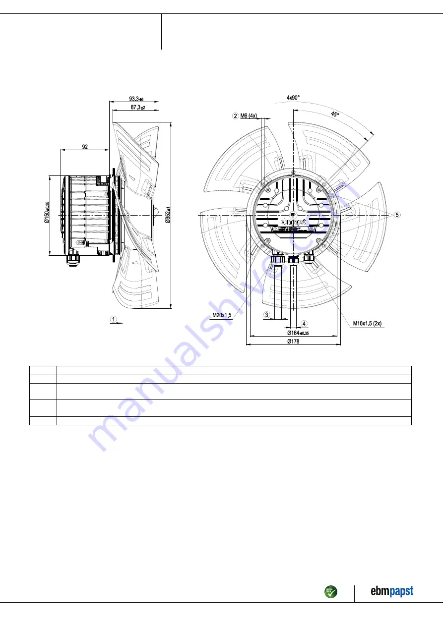
3.1 Product drawing
All dimensions in mm.
1
Direction of air flow "A"
2
Max. clearance for screw 16 mm
3
Cable diameter min. 8 mm, max. 12 mm, tightening torque 1.8±0.3 Nm (use must be made of seal provided)
Cable diameter min. 4 mm, max. 10 mm, tightening torque 1.8±0.3 Nm
4
Cable diameter min. 6 mm, max. 10 mm, tightening torque 1.8±0.3 Nm (use must be made of seal provided)
Cable diameter min. 4 mm, max. 7 mm, tightening torque 1.8±0.3 Nm
5
Tightening torque 1.5 ± 0.2 Nm
Item no. 54227-5-9970 · ENU · Change 222738 · Approved 2021-02-01 · Page 4 / 12
ebm-papst Mulfingen GmbH & Co. KG · Bachmühle 2 · D-74673 Mulfingen · Phone +49 (0) 7938 81-0 · Fax +49 (0) 7938 81-110 · info1@de.ebmpapst.com · www.ebmpapst.com


