background image

Operating instructions

A3G500-AN33-03

Translation of the original operating instructions

Fig. 3: Fan installed lying flat, cable routed in a U-shaped loop.

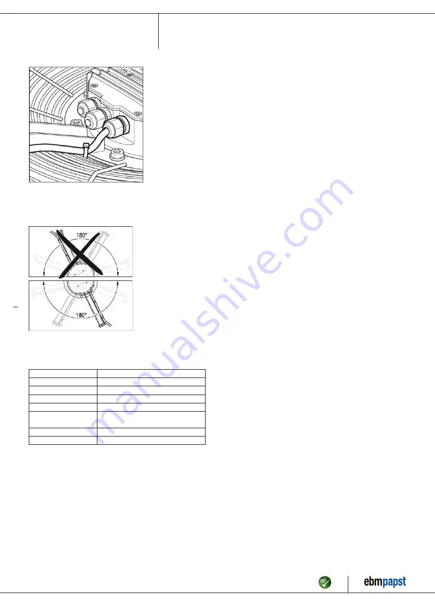
Fans installed upright

When routing the cable, make sure that the cable glands are located at
the bottom. The cables must always be routed downward.

Fig. 4: Cable routing for fans installed upright.

4.4 Factory settings

Factory settings made for the device by ebm-papst.

Mode

PWM control

Group address

1

Fan/device address

1

Max. PWM / %

100

Min. PWM / %

0

Save set value to
EEPROM

Yes

Set value requirement

Analog

Direction of action

Positive (heating)

Item no. 50313-5-9970 · ENU · Change 205336 · Approved 2020-10-01 · Page 9 / 13

ebm-papst Mulfingen GmbH & Co. KG · Bachmühle 2 · D-74673 Mulfingen · Phone +49 (0) 7938 81-0 · Fax +49 (0) 7938 81-110 · info1@de.ebmpapst.com · www.ebmpapst.com

Summary of Contents for A3G500-AN33-03

Page 1: ...ecialists are permitted to install the device to carry out a test run and to perform work on the electrical installation 1 3 Basic safety rules 1 1 3 Basic safety rules The safety hazards associated w...

Page 2: ...contact Before working on the system machine wait until all parts have come to a standstill DANGER Ejected parts Missing protective devices may cause balancing weights or broken fan blades to be eject...

Page 3: ...all protective devices Following the operating instructions Improper use In particular operating the device in the following ways is prohibited and could be hazardous Operating the device in an unbala...

Page 4: ...on of air flow V 2 Max clearance for screw 16 mm 3 Cable diameter min 4 mm max 10 mm tightening torque 2 5 0 4 Nm 4 Tightening torque 3 5 0 5 Nm Item no 50313 5 9970 ENU Change 205336 Approved 2020 10...

Page 5: ...000 Pa Data obtained at optimum efficiency level The ErP data is determined using a motor impeller combination in a standardized measurement setup 3 4 Technical description Weight 9 4 kg Size 500 mm M...

Page 6: ...neer or operator owner of the device to ensure if necessary after consultation with the network operator that this device is only connected to a connection point with a Ssc value that is greater than...

Page 7: ...n circuit must be verified in the end application Depending on the installation situation it may be necessary to connect an additional protective earth conductor by way of the extra protective earth t...

Page 8: ...not included in scope of delivery into the terminal box First connect the PE protective earth Connect the wires to the corresponding terminals Use a screwdriver to do so When connecting ensure that no...

Page 9: ...ig 4 Cable routing for fans installed upright 4 4 Factory settings Factory settings made for the device by ebm papst Mode PWM control Group address 1 Fan device address 1 Max PWM 100 Min PWM 0 Save se...

Page 10: ...evel KL3 2 8 GND Reference ground for control interface SELV KL3 3 7 0 10 V Use control current sensor value input 0 10 VDC impedance 100 k only as alternative to 4 20 mA input SELV KL3 4 10 V Voltage...

Page 11: ...e for maintenance Switch off the device via the control input Do not switch the motor e g in cyclic operation on and off via power supply Disconnect the device from the power supply When disconnecting...

Page 12: ...aning To ensure a long service life check the fans regularly for proper operation and soiling The frequency of checking is to be adapted accordingly depending on the degree of soiling DANGER Risk of i...

Page 13: ...ntry specific legal requirements Always observe the applicable country specific legal regulations with regard to the disposal of products or waste occurring in the various phases of the life cycle The...

Reviews: