background image

Operating instructions

A3G800-AG02-04

Translation of the original operating instructions

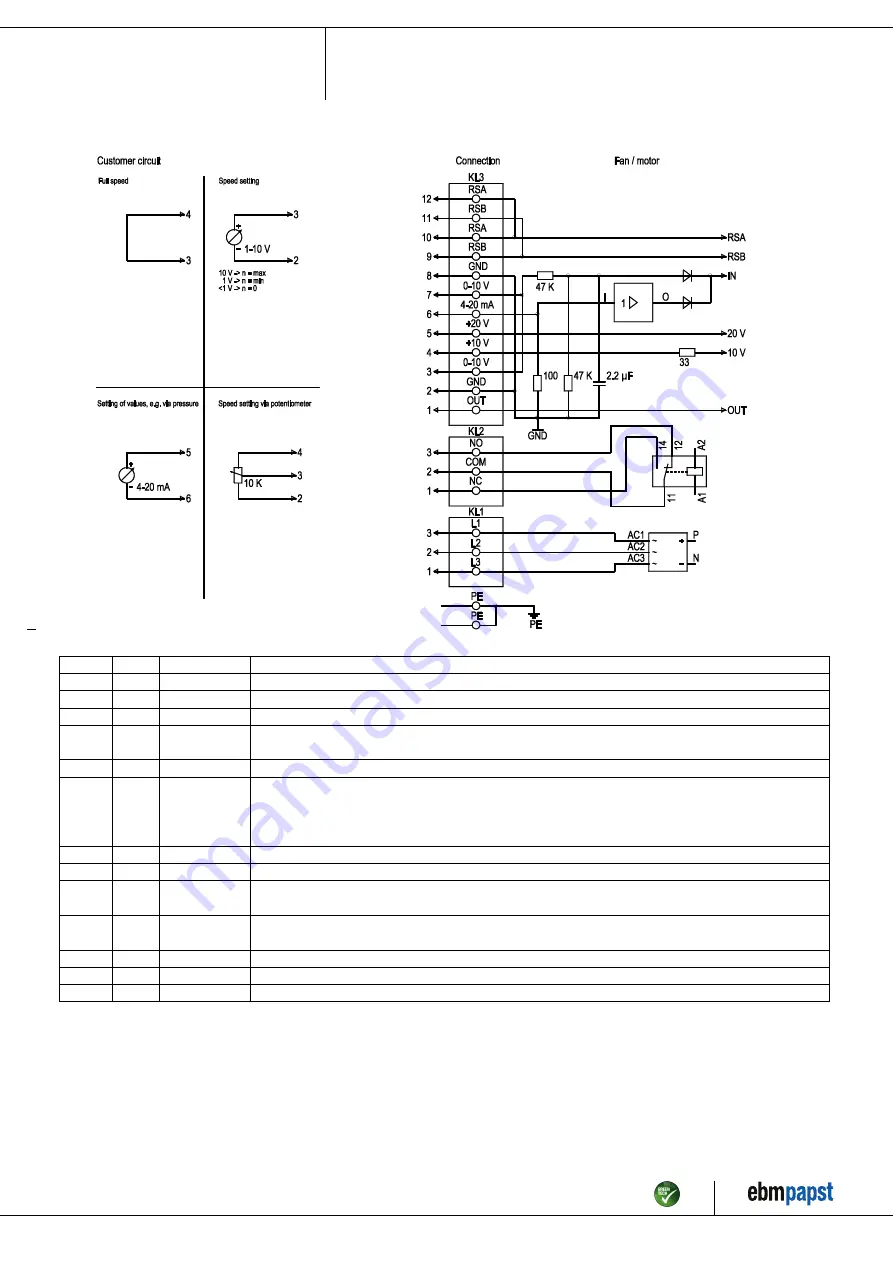
4.5 Connection screen

No.

Conn.

Designation

Function / assignment

PE

PE

Protective earth connection

KL1

1, 2, 3

L1, L2, L3

Supply voltage, 50/60 Hz

KL2

1

NC

Floating status message contact, normally closed connection

KL2

2

COM

Floating status message contact, changeover contact, common connection (2 A, max. 250 VAC,
min. 10 mA, AC1)

KL2

3

NO

Floating status message contact, normally open connection

KL3

1

OUT

Analog output, 0-10 VDC, max. 3 mA, SELV,
output of the current level control coefficient:
1 V equates to 10 % level control coefficient.
10 V equate to 100 % level control coefficient.

KL3

2, 8

GND

Reference mass for control interface, SELV

KL3

3, 7

0-10 V

Use control / actual value input 0-10 VDC, impedance 100 kΩ only as alternative to 4-20 mA input, SELV

KL3

4

+10 V

Voltage output 10 VDC (+/-3 %), max. 10 mA, supply voltage for ext. devices
(e.g. potentiometers), SELV

KL3

5

+20 V

Voltage output 20 VDC (+25 %/-10 %), max. 50 mA, supply voltage for ext. devices
(e.g. sensors), SELV

KL3

6

4-20 mA

Use control / actual value input 4-20 mA, impedance 100 Ω, only as alternative to 0-10 V input, SELV

KL3

9, 11

RSB

RS485 interface for ebmBus, RSB, SELV

KL3

10, 12

RSA

RS485 interface for ebmBus, RSA, SELV

Item no. 50472-5-9970 · Revision 82539 · Release 2014-05-08 · Page 9 / 12

ebm-papst Mulfingen GmbH & Co. KG · Bachmühle 2 · D-74673 Mulfingen · Phone +49 (0) 7938 81-0 · Fax +49 (0) 7938 81-110 · info1@de.ebmpapst.com · www.ebmpapst.com

Summary of Contents for A3G800-AG02-04

Page 1: ...rry out a test run and to perform work on the electrical installation 1 3 Basic safety rules 1 1 3 Basic safety rules Any safety hazards stemming from the device must be re evaluated once it is instal...

Page 2: ...DANGER Flying parts Missing safety devices may cause balancing weights or broken fan blades to be ejected at high speeds causing bodily harm Take appropriate safety measures WARNING Rotating device Lo...

Page 3: ...arly prohibited and may cause hazards Operating the device with an imbalance e g caused by dirt deposits or icing Operation in medical equipment with a life sustaining or lifesaving function Operation...

Page 4: ...1 Direction of air flow A 2 Cable diameter min 4 mm max 10 mm tightening torque 4 0 6 Nm 3 Depth of screw max 25 mm 4 Tightening torque 3 5 0 5 Nm Item no 50472 5 9970 Revision 82539 Release 2014 05...

Page 5: ...rotor on bottom rotor on top on request Condensate discharge holes Rotor side Operation mode S1 Motor bearing Ball bearing Technical features PFC passive Control input 0 10 VDC PWM Over temperature pr...

Page 6: ...ther Check the device for transport damage Damaged devices must no longer be installed Install the undamaged device according to your application 4 2 Connecting the electrical system DANGER Electric v...

Page 7: ...ross section VDE UL VDE mm AWG 3 PE AC 380 480 VAC 16 A 15 A C16A 1 5 16 3 PE AC 380 480 VAC 20 A 20 A C20A 2 5 14 3 PE AC 380 480 VAC 25 A 25 A C25A 4 0 12 3 PE AC 380 480 VAC 32 A 30 A C32A 6 0 10 A...

Page 8: ...nnecting the wires to terminals Seal the terminal box 4 3 3 Cable routing No water may penetrate along the cable in the direction of the cable gland Fans installed lying flat Make sure that the cable...

Page 9: ...quate to 100 level control coefficient KL3 2 8 GND Reference mass for control interface SELV KL3 3 7 0 10 V Use control actual value input 0 10 VDC impedance 100 k only as alternative to 4 20 mA input...

Page 10: ...remove any that are found Apply the nominal voltage to the voltage supply Start the device by changing the input signal 4 8 Switching off the device Switching off the device during operation Switch of...

Page 11: ...ge Switch off de energise and remove mechanical blockage Mains supply voltage faulty Check mains supply voltage restore power supply Important The error message resets automatically The device starts...

Page 12: ...tive casing against accidental contact for damage and to ensure that it is intact Visual inspection At least every 6 months Repair or replacement of the device Check the device for damage to blades an...

Reviews: