


Operating instructions
A4D500-AJ03-02
Translation of the original operating instructions
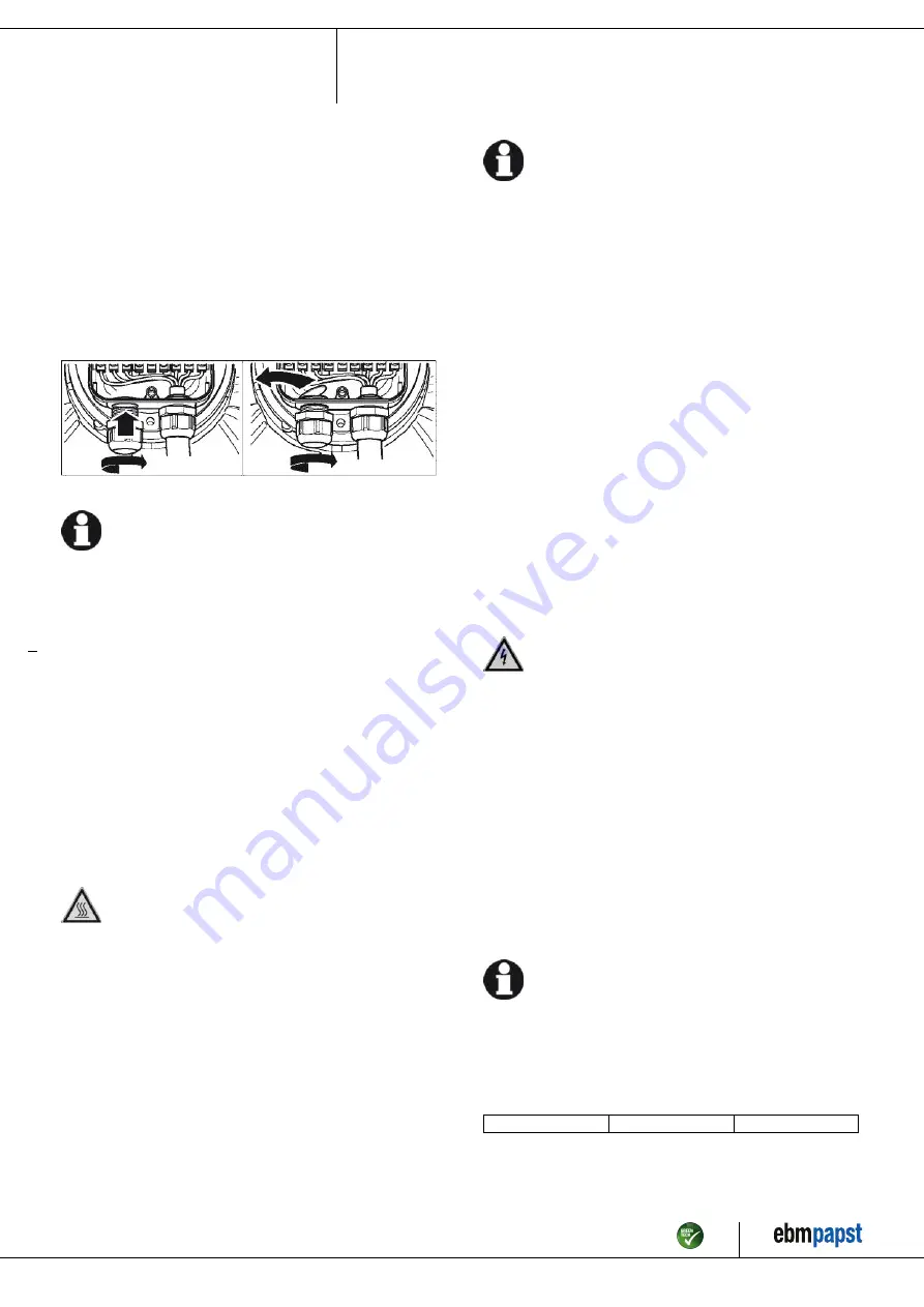
4.5 Opening additional cable glands
A second cable gland opening can be made in the terminal box.
WARNING
In the event of a fault, the cable gland is energized
Electric shock
→ Do not use metal cable glands with plastic terminal boxes.
;
Screw the cable gland into the precut thread using a wrench. When
doing so, take note of the tightening torques; see Chapter 3.1 Product
drawing.
;
Remove the plastic tab that fell off inside the terminal box when it was
penetrated.
Fig. 4: Cable gland opening
NOTE
Tightness and strain relief are dependent on the cable
used.
→ This must be checked by the user.
4.6 Checking connections
;
Ensure isolation from supply (all phases).
;
Make sure a restart is impossible
;
Check the cables for proper fit.
;
Screw the terminal box cover back on again. Terminal box tightening
torque, see Chapter 3.1 Product drawing.
;
Make sure the terminal box is completely closed and sealed and that
all screws and cable glands have been properly tightened.
4.7 Switching on the device
The device may only be switched on if it has been installed properly and
in accordance with its intended use, including the required safety
mechanisms and professional electrical hookup. This also applies for
devices which have already been equipped with plugs and terminals or
similar connectors by the customer.
WARNING
Hot motor housing
Risk of fire
→ Ensure that no combustible or flammable materials are
located close to the fan.
;
Before switching on, check the device for visible external damage
and make sure the protective devices are functional.
;
Check the fan's air flow paths for foreign matter and remove any
foreign matter found.
;
Apply the nominal supply voltage.
NOTE
Damage to the device from vibration
Bearing damage, shorter service life
→ Low-vibration operation of the fan must be ensured over the
entire speed control range.
→ Severe vibration can arise for instance from inexpert
handling, transportation damage and resultant imbalance or
be caused by component or structural resonance.
→ Speed ranges with excessively high vibration levels and
possibly resonant frequencies must be determined in the
course of fan commissioning.
→ Either run through the resonant range as quickly as
possible with speed control or find another remedy.
→ Operation with excessively high vibration levels can
lead to premature failure.
4.8 Switching off the device
;
Disconnect the device from the power supply at the supply line's
main switch.
;
When disconnecting, be sure to disconnect the ground connection last.
5. MAINTENANCE, MALFUNCTIONS, POSSIBLE
CAUSES AND REMEDIES
Do not perform any repairs on your device. Send the device to ebm-
papst for repair or replacement.
WARNING
Live terminals and connections even with device
switched off
Electric shock
→ Wait five minutes after disconnecting the voltage at all poles
before opening the device.
CAUTION
The motor restarts automatically when operating voltage
is applied, e.g. after a power failure.
Risk of injury
→ Keep out of the device's danger zone.
→ When working on the device, switch off the line voltage
and ensure that it cannot be switched back on.
→ Wait until the device comes to a stop.
→ Install the externally wired thermal overload protector in
the control circuit so that following a malfunction the motor
does not switch on again automatically after cooling off.
NOTE
If the device is not operated for a lengthy period in installed
condition in a dry environment, it is to be started up and
operated at full speed for one hour at least every four months. If
the device is not operated for a lengthy period in installed
condition in a damp environment (e.g. outdoors), it is to be
started up and operated at full speed for at least two hours once
a month to move the bearings and allow any condensate that
may have ingressed to evaporate.
Malfunction/fault
Possible cause
Possible remedy
Item no. 10044-5-9970 · ENU · Change 205900 · Approved 2020-03-10 · Page 10 / 12
ebm-papst Mulfingen GmbH & Co. KG · Bachmühle 2 · D-74673 Mulfingen · Phone +49 (0) 7938 81-0 · Fax +49 (0) 7938 81-110 · info1@de.ebmpapst.com · www.ebmpapst.com


