
Operating instructions
A4E315-AC08-09
Translation of the original operating instructions
4. CONNECTION AND STARTUP
4.1 Mechanical connection
CAUTION
Cutting and crushing hazard when removing fan from
packaging
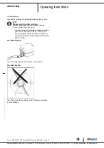
→ Carefully remove the device from its packaging, grasping it
by only the blades near the hub. Strictly avoid shocks.
→ Wear safety shoes and cut-resistant safety gloves.
NOTE
Damage to the device from vibration
Bearing damage, shorter service life
→ The fan must not be subjected to force or excessive vibration
from sections of the installation. #If the fan is connected to air
ducts, the connection should be isolated from vibration, e.g.
using compensators or similar elements. #Ensure stress-free
attachment of the fan to the substructure.
;
Check the device for transport damage. Damaged devices are not to
be installed.
;
Install the undamaged device in accordance with your application.
CAUTION
Possible damage to the device
If the device slips during installation, serious damage can result.
→ Ensure that the device is securely positioned at its place of
installation until all fastening screws have been tightened.
●
The fan must not be strained on fastening.
4.2 Electrical connection
DANGER
Voltage on the device
Electric shock
→ Always connect a protective earth first.
→ Check the protective earth.
DANGER
Faulty insulation
Risk of fatal injury from electric shock
→ Use only cables that meet the specified installation
regulations for voltage, current, insulation material, capacity,
etc.
→ Route cables so that they cannot be touched by any
rotating parts.
CAUTION
Voltage
The fan is a built-in component and has no disconnecting switch.
→ Only connect the fan to circuits that can be switched off with
an all-pole disconnection switch.
→ When working on the fan, secure the system/machine in
which the fan is installed so as to prevent it from being
switched back on.
NOTE
Water ingress into wires or cables
Water ingress at the customer end of the cable can damage the
device.
→ Make sure the end of the cable is connected in a dry
environment.
Only connect the device to circuits that can be switched off with
an all-pole disconnection switch.
4.2.1 Requirements
;
Check whether the information on the nameplate matches the
connection data.
;
If the motor run capacitor was not installed by ebm-papst, check
whether the information on the motor run capacitor matches the
information on the nameplate.
;
Before connecting the device, make sure the power supply matches
the device voltage.
;
Only use cables designed for the current level indicated on the
nameplate.
For determining the cross-section, note the sizing criteria according
to EN 61800-5-1. The protective earth must have a cross-section
equal to or greater than that of the phase conductor.
We recommend the use of 105 °C cables. Ensure that the minimum
cable cross-section is at least
AWG 26 / 0.13 mm².
Protective earth contact resistance according to EN 60335
Compliance with the resistance specifications according to EN 60335 for
the protective earth connection circuit must be verified in the end
application. Depending on the installation situation, it may be necessary
to connect an additional protective earth conductor by way of the extra
protective earth terminal provided on the device.
4.2.2 Voltage control
NOTE
Current overshoots may occur if speed control is implemented
by transformers or electronic voltage regulators (e.g. phase
control). Depending on the type of installation of the device,
noise and vibration may also occur in the case of phase
control. Vibration can lead to bearing damage and thus
premature failure.
4.2.3 Variable frequency drive
Please use a variable frequency drive only after consultation with ebm-
papst.
For operation with variable frequency drives, install sinusoidal
filters that work on all poles (phase-phase and phase-ground)
between the drive and the motor.
During operation with variable frequency drives, an all-pole
sine filter protects the motor against high-voltage transients that
can destroy the coil insulation system, and against harmful
bearing currents.
Heating of the motor due to use of a variable frequency drive must be
checked in the application by the customer.
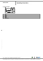
4.3 Connecting the cables
The device has external leads.
;
First connect the "PE" (protective earth).
●
Connect the cables according to your application. When doing so,
observe Chapter 4.4 Connection diagram.
Item no. 12476-5-9970 · ENU · Change 98705 · Approved 2018-04-26 · Page 6 / 10
ebm-papst Mulfingen GmbH & Co. KG · Bachmühle 2 · D-74673 Mulfingen · Phone +49 (0) 7938 81-0 · Fax +49 (0) 7938 81-110 · info1@de.ebmpapst.com · www.ebmpapst.com


