background image

Operating instructions

A4E400-AP02-01

Translation of the original operating instructions
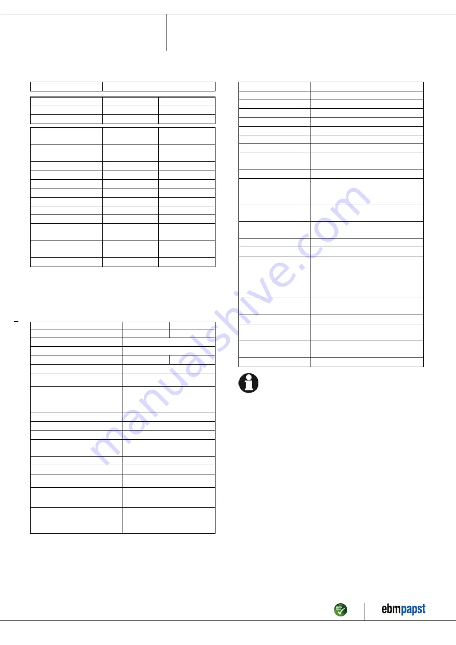
3.2 Nominal data

Motor

M4E074-EI

Phase

1~

1~

Nominal voltage / VAC

230

230

Frequency / Hz

50

60

Method of obtaining
data

fa

fa

Valid for approval/
standard

CE

CE

Speed (rpm) / min

-1

1430

1700

Power consumption / W

160

240

Current draw / A

0.73

1.06

Capacitor / µF

6

6

Capacitor voltage / VDB

400

400

Capacitor standard

S0 (CE)

S0 (CE)

Max. back pressure / Pa

110

75

Min. ambient
temperature / °C

-25

-25

Max. ambient
temperature / °C

40

40

Starting current / A

2.0

1.9

ml = Max. load · me = Max. efficiency · fa = Free air

cs = Customer specification · ce = Customer equipment

Subject to change

3.3 Data according to Commission Regulation (EU) 327/
2011

Actual

Req. 2015

01 Overall efficiency η

es

/ %

34

29.4

02 Measurement category

A

03 Efficiency category

Static

04 Efficiency grade N

44.6

40

05 Variable speed drive

No

06 Year of manufacture

The year of manufacture is specified on the
product's rating label.

07 Manufacturer

ebm-papst Mulfingen GmbH & Co. KG
Amtsgericht (court of registration) Stuttgart ·
HRA 590344
D-74673 Mulfingen

08 Type

A4E400-AP02-01

09 Power consumption P

e

/ kW

0.21

09 Air flow q

v

/ m³/h

2695

09 Pressure increase total p

sf

/

Pa

96

10 Speed (rpm) n / min

-1

1390

11 Specific ratio

*

1.00

12 Recycling/disposal

Information on recycling and disposal is
provided in the operating instructions.

13 Maintenance

Information on installation, operation and
maintenance is provided in the operating
instructions.

14 Additional components

Components used to calculate the energy
efficiency that are not apparent from the
measurement category are detailed in the
CE declaration.

*

Specific ratio = 1 + p

fs

/ 100 000 Pa

Data obtained at optimum efficiency level. The ErP data is determined using a motor-impeller

combination in a standardized measurement setup.

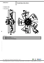
3.4 Technical description

Weight

4.12 kg

Size

400 mm

Motor size

74

Rotor surface

Painted black

Blade material

Sheet steel, painted black

Number of blades

5

Airflow direction

V

Direction of rotation

Counterclockwise, viewed toward rotor

Degree of protection

IP44; installation- and position-dependent
as per EN 60034-5

Insulation class

"B"

Moisture (F) /
Environmental (H)
protection class

H1

Installation position

Shaft horizontal or rotor on bottom; rotor
on top on request

Condensation
drainage holes

On rotor side

Mode

S1

Motor bearing

Ball bearing

Touch current
according to IEC
60990 (measuring
circuit Fig. 4, TN
system)

< 0.75 mA

Motor protection

Thermal overload protector (TOP)
internally connected

with cable

Variable

Protection class

I (with customer connection of protective
earth)

Conformity with
standards

EN 60335-1; CE

Approval

CCC; EAC

With regard to cyclic speed loads, note that the rotating parts of
the device are designed for a maximum of one million load
cycles. If you have special questions, consult ebm-papst for
support.

;

Use the device in accordance with its degree of protection.

Information on surface quality

The surfaces of the products conform to the generally applicable industrial
standard. The surface quality may change during the production period.
This has no effect on strength, dimensional stability and dimensional
accuracy.
The color pigments in the paints used perceptibly react to UV light over
the course of time. This does not however in any way affect the
technical properties of the products. The product is to be protected against
UV radiation to prevent the formation of patches and fading. Changes in
color are not a reason for complaint and are not covered by the warranty.

Item no. 10320-5-9970 · ENU · Change 205161 · Approved 2019-10-23 · Page 5 / 11

ebm-papst Mulfingen GmbH & Co. KG · Bachmühle 2 · D-74673 Mulfingen · Phone +49 (0) 7938 81-0 · Fax +49 (0) 7938 81-110 · info1@de.ebmpapst.com · www.ebmpapst.com

Summary of Contents for A4E400-AP02-01

Page 1: ...ned and authorized technical staff Only authorized specialists are permitted to install the device to carry out a test run and to perform work on the electrical installation 1 3 Basic safety rules 1 1 3 Basic safety rules The safety hazards associated with the device must be assessed again following installation in the final product The locally applicable industrial safety regulations are always t...

Page 2: ...the entire setup is EMC compliant 1 7 Mechanical movement DANGER Rotating device Risk of injury to body parts coming into contact with the rotor or the impeller Secure the device against accidental contact Before working on the system machine wait until all parts have come to a standstill WARNING Rotating device Long hair and dangling items of clothing jewelry and the like can become entangled and...

Page 3: ...ting the device in an unbalanced state e g due to dirt deposits or ice formation Resonant operation operation with severe vibration This also includes vibration transmitted to the fan from the customer installation Operation in medical equipment with a life sustaining or life support function Conveying solids in the flow medium Painting the device Connections e g screws coming loose during operati...

Page 4: ...ll dimensions in mm 1 Direction of air flow V 2 Max clearance for screw 10 mm 3 Cable PVC 4G 0 5 mm 4x crimped splices Item no 10320 5 9970 ENU Change 205161 Approved 2019 10 23 Page 4 11 ebm papst Mulfingen GmbH Co KG Bachmühle 2 D 74673 Mulfingen Phone 49 0 7938 81 0 Fax 49 0 7938 81 110 info1 de ebmpapst com www ebmpapst com ...

Page 5: ... in a standardized measurement setup 3 4 Technical description Weight 4 12 kg Size 400 mm Motor size 74 Rotor surface Painted black Blade material Sheet steel painted black Number of blades 5 Airflow direction V Direction of rotation Counterclockwise viewed toward rotor Degree of protection IP44 installation and position dependent as per EN 60034 5 Insulation class B Moisture F Environmental H pro...

Page 6: ...shock Use only cables that meet the specified installation regulations for voltage current insulation material capacity etc Route cables so that they cannot be touched by any rotating parts DANGER Electrical charge 50 µC between phase conductor and protective earth connection after switching off supply with multiple devices connected in parallel Electric shock risk of injury Ensure sufficient prot...

Page 7: ... checked by the customer following installation in the end device 4 2 3 Variable frequency drive Please use a variable frequency drive only after consultation with ebm papst For operation with variable frequency drives install sinusoidal filters that work on all poles phase phase and phase ground between the drive and the motor During operation with variable frequency drives an all pole sine filte...

Page 8: ...uctions 4 4 Connection diagram U1 blue Z brown U2 black PE green yellow Item no 10320 5 9970 ENU Change 205161 Approved 2019 10 23 Page 8 11 ebm papst Mulfingen GmbH Co KG Bachmühle 2 D 74673 Mulfingen Phone 49 0 7938 81 0 Fax 49 0 7938 81 110 info1 de ebmpapst com www ebmpapst com ...

Page 9: ... MAINTENANCE MALFUNCTIONS POSSIBLE CAUSES AND REMEDIES Do not perform any repairs on your device Send the device to ebm papst for repair or replacement WARNING Live terminals and connections even with device switched off Electric shock Wait five minutes after disconnecting the voltage at all poles before opening the device CAUTION Electric charge on capacitor after device is switched off Electric ...

Page 10: ...ing the protective earth terminal Visual inspection At least every 6 months Fasten Insulation of cables for damage Visual inspection At least every 6 months Replace cables Condensation drainage holes for clogging where necessary Visual inspection At least every 6 months Open holes Welds for crack formation Visual inspection At least every 6 months Replace device Abnormal bearing noise acoustic At ...

Page 11: ...materials and are therefore to be treated in the same manner The materials concerned are as follows Miscellaneous insulators used in the terminal box Power cables Cables for internal wiring Electrolytic capacitors Dispose of electronic components employing the proper procedures for electronic scrap Please contact ebm papst for any other questions on disposal Item no 10320 5 9970 ENU Change 205161 ...

Reviews: