
Operating instructions
A4E400-AP02-01
Translation of the original operating instructions
3.5 Mounting data
Strength class of
screws
8.8
For screw clearance, see Chapter 3.1 Product drawing
;
Secure the screws against unintentional loosening (e.g. use self-
locking screws).
Any further mounting data required can be taken from the product
drawing or Section Chapter 4.1 Mechanical connection.
3.6 Transport and storage conditions
Max. permitted
ambient temp. for
motor (transport/
storage)
+ 80 °C
Min. permitted
ambient temp. for
motor (transport/
storage)
- 40 °C
4. CONNECTION AND STARTUP
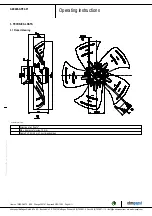
4.1 Mechanical connection
CAUTION
Cutting and crushing hazard when removing fan from
packaging
→ Carefully remove the device from its packaging, grasping it
by only the blades near the hub. Strictly avoid shocks.
→ Wear safety shoes and cut-resistant safety gloves.
NOTE
Damage to the device from vibration
Bearing damage, shorter service life
→ The fan must not be subjected to force or excessive vibration
from sections of the installation.
→ If the fan is connected to air ducts, the connection should
be isolated from vibration, e.g. using compensators or similar
elements.
→ Ensure stress-free attachment of the fan to the
substructure.
;
Check the device for transport damage. Damaged devices are not to
be installed.
;
Install the undamaged device in accordance with your application.
CAUTION
Possible damage to the device
If the device slips during installation, serious damage can result.
→ Ensure that the device is securely positioned at its place of
installation until all fastening screws have been tightened.
●
The fan must not be strained on fastening.
4.2 Electrical connection
DANGER
Voltage on the device
Electric shock
→ Always connect a protective earth first.
→ Check the protective earth.
DANGER
Faulty insulation
Risk of fatal injury from electric shock
→ Use only cables that meet the specified installation
regulations for voltage, current, insulation material, capacity,
etc.
→ Route cables so that they cannot be touched by any
rotating parts.
DANGER
Electrical charge (>50 µC) between phase conductor and
protective earth connection after switching off supply
with multiple devices connected in parallel.
Electric shock, risk of injury
→ Ensure sufficient protection against accidental contact.
Before working on the electrical hookup, short the supply
and PE connections.
CAUTION
Voltage
The fan is a built-in component and has no disconnecting switch.
→ Only connect the fan to circuits that can be switched off with
an all-pole disconnection switch.
→ When working on the fan, secure the system/machine in
which the fan is installed so as to prevent it from being
switched back on.
NOTE
Water ingress into wires or cables
Water ingress at the customer end of the cable can damage the
device.
→ Make sure the end of the cable is connected in a dry
environment.
Only connect the device to circuits that can be switched off with
an all-pole disconnection switch.
4.2.1 Requirements
;
Check whether the information on the nameplate matches the
connection data.
;
If the motor run capacitor was not installed by ebm-papst, check
whether the information on the motor run capacitor matches the
information on the nameplate.
;
Before connecting the device, make sure the power supply matches
the device voltage.
;
Only use cables designed for the current level indicated on the
nameplate.
For determining the cross-section, note the sizing criteria according
to EN 61800-5-1. The protective earth must have a cross-section
equal to or greater than that of the phase conductor.
We recommend the use of 105 °C cables. Ensure that the minimum
cable cross-section is at least
AWG 26 / 0.13 mm².
Item no. 10320-5-9970 · ENU · Change 205161 · Approved 2019-10-23 · Page 6 / 11
ebm-papst Mulfingen GmbH & Co. KG · Bachmühle 2 · D-74673 Mulfingen · Phone +49 (0) 7938 81-0 · Fax +49 (0) 7938 81-110 · info1@de.ebmpapst.com · www.ebmpapst.com


