


Operating instructions
A4E400-AP02-14
Translation of the original operating instructions
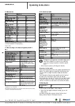
3. TECHNICAL DATA
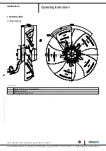
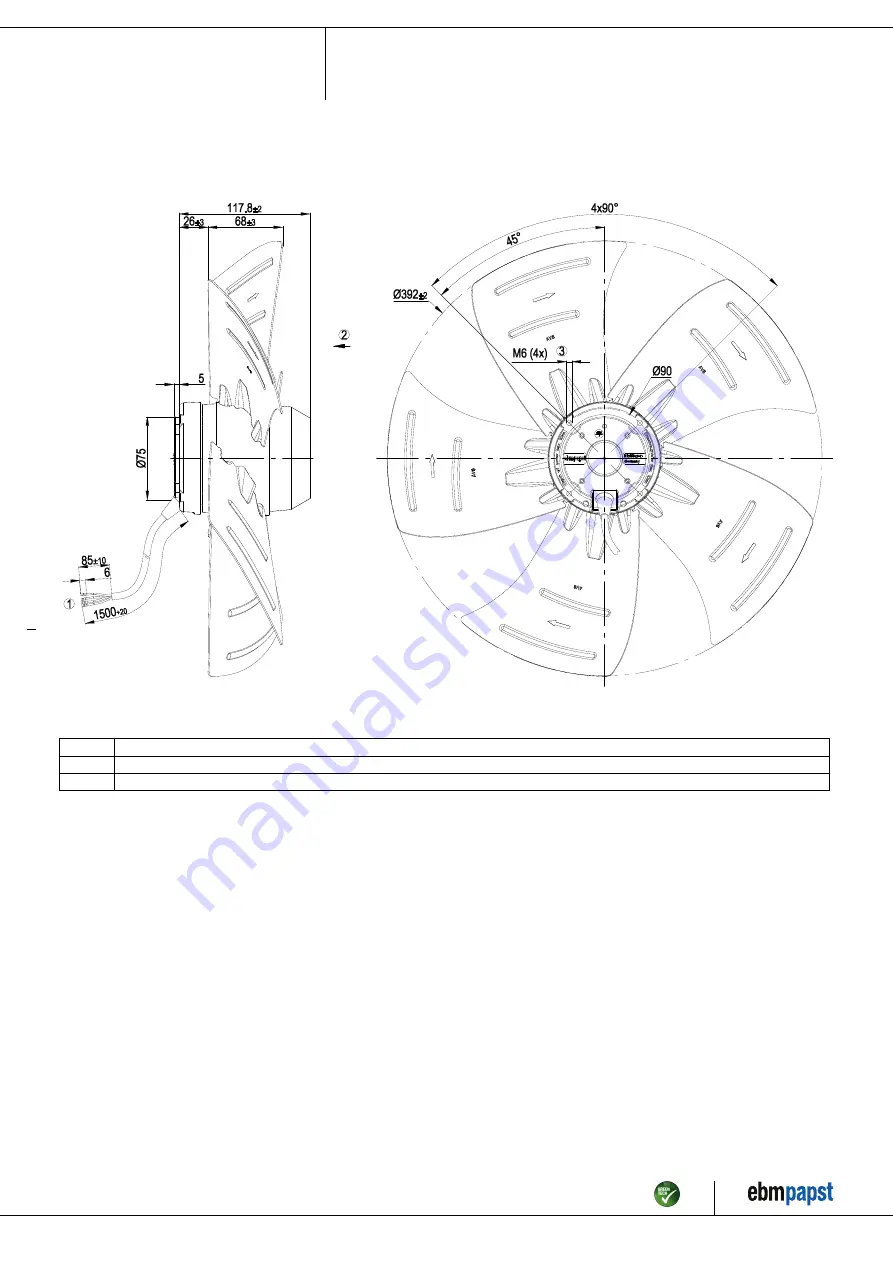
3.1 Product drawing
All dimensions in mm.
1
Cable PVC 4G 0.5 mm², 4x crimped splices
2
Direction of air flow "V"
3
Max. clearance for screw 10 mm
Item no. 11692-5-9970 · ENU · Change 205353 · Approved 2019-11-27 · Page 4 / 11
ebm-papst Mulfingen GmbH & Co. KG · Bachmühle 2 · D-74673 Mulfingen · Phone +49 (0) 7938 81-0 · Fax +49 (0) 7938 81-110 · info1@de.ebmpapst.com · www.ebmpapst.com


