background image

Operating instructions

A6D630-AM01-02

Translation of the original operating instructions
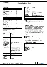
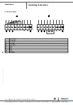
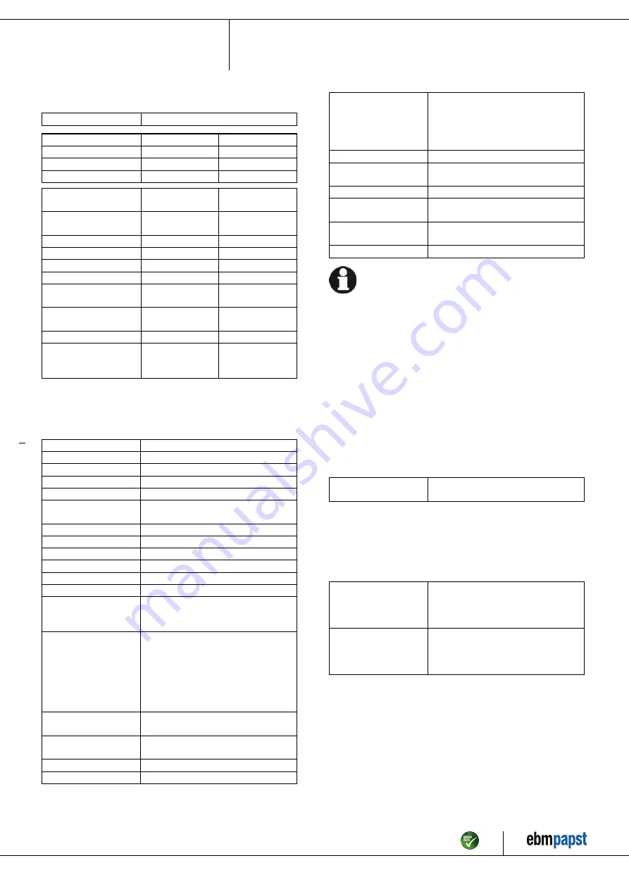
3.2 Nominal data

Motor

M6D110-GF

Phase

3~

3~

Nominal voltage / VAC

400

400

Wiring

Δ

Y

Frequency / Hz

50

50

Method of obtaining
data

ml

ml

Valid for approval/
standard

-

-

Speed (rpm) / min

-1

850

620

Power consumption / W

740

440

Current draw / A

1.38

0.76

Max. back pressure / Pa

100

54

Min. ambient
temperature / °C

-40

-40

Max. ambient
temperature / °C

60

60

Starting current / A

4

Max. safe operating
speed (rpm) /
min

-1

1150
@ 80 °C

1150
@ 80 °C

ml = Max. load · me = Max. efficiency · fa = Free air

cs = Customer specification · ce = Customer equipment

Subject to change

3.3 Technical description

Weight

10.4 kg

Size

630 mm

Motor size

110

Rotor surface

Cast in aluminum

Terminal box material

PP plastic

Blade material

Sheet aluminum insert, sprayed with PP
plastic

Number of blades

5

Blade pitch

Airflow direction

A

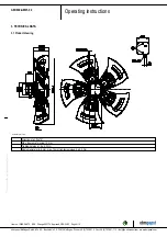
Direction of rotation

Clockwise, viewed toward rotor

Degree of protection

IP54

Insulation class

"F"

Moisture (F) /
Environmental (H)
protection class

H2

Ambient temperature
note

Occasional start-up at temperatures
between -40°C and -25°C is permitted.
For continuous operation at ambient
temperatures below -25°C (such as
refrigeration applications), use must be
made of a fan design with special low-
temperature bearings.

Installation position

Shaft horizontal or rotor on bottom; rotor
on top on request

Condensation
drainage holes

On rotor side

Mode

S1

Motor bearing

Ball bearing

Touch current
according to IEC
60990 (measuring
circuit Fig. 4, TN
system)

<= 3.5 mA

Electrical hookup

Terminal box

Motor protection

Thermal overload protector (TOP) with
basic insulation

with cable

Axial

Protection class

I (with customer connection of protective
earth)

Conformity with
standards

EN 60034-1 (2010)

Approval

VDE; EAC

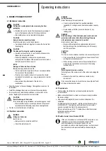
With regard to cyclic speed loads, note that the rotating parts of
the device are designed for a maximum of one million load
cycles. If you have special questions, consult ebm-papst for
support.

;

Use the device in accordance with its degree of protection.

Information on surface quality

The surfaces of the products conform to the generally applicable industrial
standard. The surface quality may change during the production period.
This has no effect on strength, dimensional stability and dimensional
accuracy.
The color pigments in the paints used perceptibly react to UV light over
the course of time. This does not however in any way affect the
technical properties of the products. The product is to be protected against
UV radiation to prevent the formation of patches and fading. Changes in
color are not a reason for complaint and are not covered by the warranty.
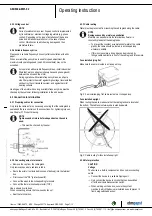
3.4 Mounting data

Strength class of
screws

8.8

;

Secure the screws against unintentional loosening (e.g. use self-
locking screws).

Any further mounting data required can be taken from the product
drawing or Section Chapter 4.1 Mechanical connection.

3.5 Transport and storage conditions

Max. permitted
ambient temp. for
motor (transport/
storage)

+80 °C

Min. permitted
ambient temp. for
motor (transport/
storage)

-40 °C

Item no. 12450-5-9970 · ENU · Change 202174 · Approved 2019-04-03 · Page 5 / 12

ebm-papst Mulfingen GmbH & Co. KG · Bachmühle 2 · D-74673 Mulfingen · Phone +49 (0) 7938 81-0 · Fax +49 (0) 7938 81-110 · info1@de.ebmpapst.com · www.ebmpapst.com

Summary of Contents for A6D630-AM01-02

Page 1: ...uitably qualified trained and authorized technical staff Only authorized specialists are permitted to install the device to carry out a test run and to perform work on the electrical installation 1 3 Basic safety rules 1 1 3 Basic safety rules The safety hazards associated with the device must be assessed again following installation in the final product The locally applicable industrial safety re...

Page 2: ...tact with the rotor or the impeller Secure the device against accidental contact Before working on the system machine wait until all parts have come to a standstill WARNING Rotating device Long hair and dangling items of clothing jewelry and the like can become entangled and be pulled into the device Injuries can result Do not wear any loose fitting or dangling clothing or jewelry while working on...

Page 3: ...ng the device in the following ways is prohibited and could be hazardous Operating the device in an unbalanced state e g due to dirt deposits or ice formation Resonant operation operation with severe vibration This also includes vibration transmitted to the fan from the customer installation Operation in medical equipment with a life sustaining or life support function Conveying solids in the flow...

Page 4: ...tion of air flow A 2 Max clearance for screw 12 mm 3 Tightening torque 1 5 0 2 Nm 4 Cable diameter min 6 mm max 12 mm tightening torque 2 0 3 Nm Item no 12450 5 9970 ENU Change 202174 Approved 2019 04 03 Page 4 12 ebm papst Mulfingen GmbH Co KG Bachmühle 2 D 74673 Mulfingen Phone 49 0 7938 81 0 Fax 49 0 7938 81 110 info1 de ebmpapst com www ebmpapst com ...

Page 5: ...l hookup Terminal box Motor protection Thermal overload protector TOP with basic insulation with cable Axial Protection class I with customer connection of protective earth Conformity with standards EN 60034 1 2010 Approval VDE EAC With regard to cyclic speed loads note that the rotating parts of the device are designed for a maximum of one million load cycles If you have special questions consult...

Page 6: ... specified installation regulations for voltage current insulation material capacity etc Route cables so that they cannot be touched by any rotating parts DANGER Electrical charge 50 µC between phase conductor and protective earth connection after switching off supply with multiple devices connected in parallel Electric shock risk of injury Ensure sufficient protection against accidental contact B...

Page 7: ...e cable gland Only remove caps where cables are fed in Route the wire s not included in scope of delivery into the terminal box First connect the PE protective earth Connect the wires to the corresponding terminals Connect the thermal overload protector TOP Use a screwdriver to do so When connecting ensure that no wire ends fan out Seal the terminal box 4 3 3 Cable routing Water must be prevented ...

Page 8: ...ipped with thermal overload protectors to protect the devices Check to make sure that the thermal overload protector is correctly connected before each operation Failure to connect the thermal overload protector correctly will invalidate your warranty claim Item no 12450 5 9970 ENU Change 202174 Approved 2019 04 03 Page 8 12 ebm papst Mulfingen GmbH Co KG Bachmühle 2 D 74673 Mulfingen Phone 49 0 7...

Page 9: ...ection Y Star connection L1 U1 black L2 V1 blue L3 W1 brown W2 yellow U2 green V2 white TOP 2x gray PE green yellow Item no 12450 5 9970 ENU Change 202174 Approved 2019 04 03 Page 9 12 ebm papst Mulfingen GmbH Co KG Bachmühle 2 D 74673 Mulfingen Phone 49 0 7938 81 0 Fax 49 0 7938 81 110 info1 de ebmpapst com www ebmpapst com ...

Page 10: ... inexpert handling transportation damage and resultant imbalance or be caused by component or structural resonance Speed ranges with excessively high vibration levels and possibly resonant frequencies must be determined in the course of fan commissioning Either run through the resonant range as quickly as possible with speed control or find another remedy Operation with excessively high vibration ...

Page 11: ...ce it Repair of load bearing or rotating parts is not permitted Operate the fan for 2 hours at maximum speed to permit the evaporation of any moisture that may have ingressed If cleaning does not eliminate vibrations the fan may need to be rebalanced To have it rebalanced contact ebm papst The fan is equipped with maintenance free ball bearings The lifetime lubrication of the ball bearings is desi...

Page 12: ...etallic materials are generally considered to be fully recyclable Separate the components for recycling into the following categories Steel and iron Aluminum Non ferrous metal e g motor windings Plastics particularly with brominated flame retardants in accordance with marking Insulating materials Cables and wires Electronic scrap e g circuit boards Only ferrite magnets and not rare earth magnets a...

Reviews: