


Operating instructions
A6D630-AO05-03
Translation of the original operating instructions
3. TECHNICAL DATA
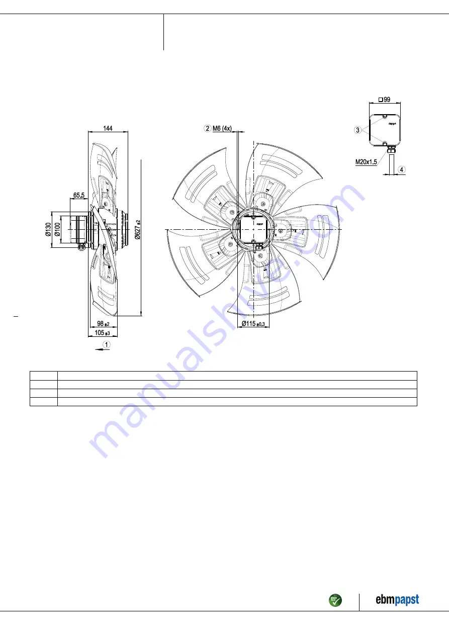
3.1 Product drawing
All dimensions in mm.
1
Airflow direction "V"
2
Max. clearance for screw 12 mm
3
Tightening torque 1.5 ± 0.2 Nm
4
Cable diameter min. 6 mm, max. 12 mm, tightening torque 2 ± 0.3 Nm
Item no. 13076-5-9970 · ENU · Change 206209 · Approved 2020-03-10 · Page 4 / 12
ebm-papst Mulfingen GmbH & Co. KG · Bachmühle 2 · D-74673 Mulfingen · Phone +49 (0) 7938 81-0 · Fax +49 (0) 7938 81-110 · info1@de.ebmpapst.com · www.ebmpapst.com


