


Operating instructions
A6D630-AO05-03
Translation of the original operating instructions
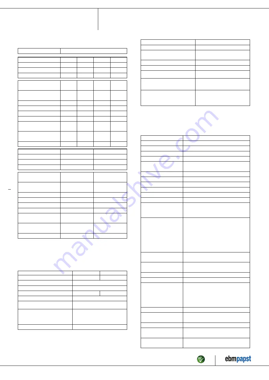
3.2 Nominal data
Motor
M6D110-GF
Phase
3~
3~
3~
3~
Nominal voltage / VAC
230
230
277
400
Wiring
Δ
Δ
Δ
Y
Frequency / Hz
50
60
60
50
Method of obtaining
data
ml
ml
ml
ml
Valid for approval/
standard
CE
CE
CE
CE
Speed (rpm) / min
-1
925
1040
1090
925
Power consumption / W
510
730
800
510
Current draw / A
2.16
2.39
2.45
1.25
Max. back pressure / Pa
100
128
140
100
Min. ambient
temperature / °C
-40
-40
-40
-40
Max. ambient
temperature / °C
65
55
55
65
Starting current / A
7.2
6.45
4.3
Phase
3~
3~
Nominal voltage / VAC
400
480
Wiring
Y
Y
Frequency / Hz
60
60
Method of obtaining
data
ml
ml
Valid for approval/
standard
CE
CE
Speed (rpm) / min
-1
1040
1090
Power consumption / W
730
800
Current draw / A
1.38
1.42
Max. back pressure / Pa
128
140
Min. ambient
temperature / °C
-40
-40
Max. ambient
temperature / °C
55
55
Starting current / A
3.9
ml = Max. load · me = Max. efficiency · fa = Free air
cs = Customer specification · ce = Customer equipment
Subject to change
3.3 Data according to Commission Regulation (EU) 327/
2011
Actual
Req. 2015
01 Overall efficiency η
es
/ %
35.3
31.8
02 Measurement category
A
03 Efficiency category
Static
04 Efficiency grade N
43.5
40
05 Variable speed drive
No
06 Year of manufacture
The year of manufacture is specified on the
product's rating label.
07 Manufacturer
ebm-papst Mulfingen GmbH & Co. KG
Amtsgericht (court of registration) Stuttgart
· HRA 590344
D-74673 Mulfingen
08 Type
A6D630-AO05-03
09 Power consumption P
e
/ kW
0.5
09 Air flow q
v
/ m³/h
6365
09 Pressure increase total p
sf
/
Pa
101
10 Speed (rpm) n / min
-1
920
11 Specific ratio
*
1.00
12 Recycling/disposal
Information on recycling and disposal is
provided in the operating instructions.
13 Maintenance
Information on installation, operation and
maintenance is provided in the operating
instructions.
14 Additional components
Components used to calculate the energy
efficiency that are not apparent from the
measurement category are detailed in the
CE declaration.
*
Specific ratio = 1 + p
fs
/ 100 000 Pa
Data obtained at optimum efficiency level. The ErP data is determined using a motor-impeller
combination in a standardized measurement setup.
3.4 Technical description
Weight
10.6 kg
Size
630 mm
Motor size
110
Rotor surface
Painted black
Terminal box material
PP plastic
Blade material
Press-fitted sheet steel blank, sprayed
with PP plastic
Number of blades
5
Blade pitch
10°
Airflow direction
V
Direction of rotation
Counterclockwise, viewed toward rotor
Degree of protection
IP54
Insulation class
"F"
Moisture (F) /
Environmental (H)
protection class
H2
Ambient temperature
note
Occasional start-up at temperatures
between -40°C and -25°C is permitted.
For continuous operation at ambient
temperatures below -25°C (such as
refrigeration applications), use must be
made of a fan design with special low-
temperature bearings.
Installation position
Shaft horizontal or rotor on bottom; rotor
on top on request
Condensation
drainage holes
On rotor side
Mode
S1
Motor bearing
Ball bearing
Touch current
according to IEC
60990 (measuring
circuit Fig. 4, TN
system)
<= 3.5 mA
Electrical hookup
Terminal box
Motor protection
Thermal overload protector (TOP) with
basic insulation
with cable
Axial
Protection class
I (with customer connection of protective
earth)
Conformity with
standards
EN 61800-5-1; CE
Item no. 13076-5-9970 · ENU · Change 206209 · Approved 2020-03-10 · Page 5 / 12
ebm-papst Mulfingen GmbH & Co. KG · Bachmühle 2 · D-74673 Mulfingen · Phone +49 (0) 7938 81-0 · Fax +49 (0) 7938 81-110 · info1@de.ebmpapst.com · www.ebmpapst.com


