background image

Operating instructions

D3G146-LV13-30

Translation of the original operating instructions

CAUTION
Voltage

The device is a built-in component and has no disconnecting
switch.
→ Only connect the device to circuits that can be switched off

with an all-pole disconnection switch.

→ When working on the device, secure the system/

machine in which the device is installed so as to prevent it
from being switched back on.

NOTE
Water ingress into wires or cables

Water ingress at the customer end of the cable can damage the
device.
→ Make sure the end of the cable is connected in a dry

environment.

Only connect the device to circuits that can be switched off with
an all-pole disconnection switch.

4.2.1 Requirements

;

Check whether the information on the nameplate matches the
connection data.

;

Before connecting the device, make sure the power supply matches
the device voltage.

;

Only use cables designed for the current level indicated on the
nameplate.
For determining the cross-section, note the sizing criteria according
to EN 61800-5-1. The protective earth must have a cross-section
equal to or greater than that of the phase conductor.
We recommend the use of 105 °C cables. Ensure that the minimum
cable cross-section is at least
AWG 26 / 0.13 mm².

Protective earth contact resistance according to EN 60335

Compliance with the resistance specifications according to EN 60335 for
the protective earth connection circuit must be verified in the end
application. Depending on the installation situation, it may be necessary
to connect an additional protective earth conductor by way of the extra
protective earth terminal provided on the device.

4.2.2 Reactive currents

Because of the EMC filter integrated for compliance with EMC
limits (interference emission and immunity to interference),
reactive currents can be measured in the supply line even
when the motor is at a standstill and the line voltage is switched
on.

The values are typically in the range < 50 mA

At the same time, the effective power in this operating state
(operational readiness) is typically < 2 W.

4.2.3 Residual current circuit breaker (RCCB)

If the use of a residual current device (RCD) is required in your
installation, only pulse-current sensitive and/or AC/DC-
sensitive residual current devices (type A or B) are
permissible. As with variable frequency drives, residual current
devices cannot provide personal safety while operating the
device. When the device power supply is switched on, pulsed
charging currents from the capacitors in the integrated EMC
filter can lead to the instant tripping of residual current devices.

We recommend the use of residual current circuit breakers
(RCCB) with a trip threshold of 300 mA and delayed tripping
(super-resistant, characteristic K).

4.2.4 Locked-rotor protection

Due to the locked-rotor protection, the starting current (LRA) is
equal to or less than the nominal current (FLA).
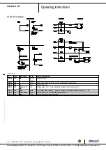
4.3 Plug connection

4.3.1 Making supply connections

;

Check your connector's pin assignment.

;

Connect the built-in connector with the mating connector.

;

Ensure that the connector is properly engaged.

Item no. 53671-5-9970 · ENU · Change 213540 · Approved 2020-07-14 · Page 7 / 11

ebm-papst Mulfingen GmbH & Co. KG · Bachmühle 2 · D-74673 Mulfingen · Phone +49 (0) 7938 81-0 · Fax +49 (0) 7938 81-110 · info1@de.ebmpapst.com · www.ebmpapst.com

Summary of Contents for D3G146-LV13-30

Page 1: ...ff Only authorized specialists are permitted to install the device to carry out a test run and to perform work on the electrical installation 1 3 Basic safety rules 1 1 3 Basic safety rules The safety hazards associated with the device must be assessed again following installation in the final product The locally applicable industrial safety regulations are always to be observed when working on th...

Page 2: ...fy that the entire setup is EMC compliant 1 7 Mechanical movement DANGER Rotating device Risk of injury to body parts coming into contact with the rotor or the impeller Secure the device against accidental contact Before working on the system machine wait until all parts have come to a standstill WARNING Rotating device Long hair and dangling items of clothing jewelry and the like can become entan...

Page 3: ... prohibited and could be hazardous Operating the device in an unbalanced state e g due to dirt deposits or ice formation Resonant operation operation with severe vibration This also includes vibration transmitted to the fan from the customer installation Operation in medical equipment with a life sustaining or life support function Conveying solids in the flow medium Painting the device Connection...

Page 4: ...ch 1 3 0 10 V lin PWM 1 4 GND 2 Connector Lumberg 3642 03 K01 pluggable with 3626 03 K01 2 1 PE 2 2 L 2 3 N 3 4x sheet metal nut for thread EN ISO 1478 ST4 8 min screw length 14 5 mm plus material thickness of attachment Item no 53671 5 9970 ENU Change 213540 Approved 2020 07 14 Page 4 11 ebm papst Mulfingen GmbH Co KG Bachmühle 2 D 74673 Mulfingen Phone 49 0 7938 81 0 Fax 49 0 7938 81 110 info1 d...

Page 5: ...al PP plastic Motor suspension Motor vibration damped on both sides Direction of rotation Counterclockwise viewed toward rotor Degree of protection Motor IP00 electronics IP20 Insulation class F Moisture F Environmental H protection class H0 dry environment Installation position Any Cooling hole opening On rotor and stator sides Mode S1 Motor bearing Ball bearing Technical features Output 10 VDC m...

Page 6: ...m vibration e g using compensators or similar elements Ensure stress free attachment of the fan to the substructure Check the device for transport damage Damaged devices are not to be installed Install the undamaged device in accordance with your application CAUTION Possible damage to the device If the device slips during installation serious damage can result Ensure that the device is securely po...

Page 7: ...tective earth conductor by way of the extra protective earth terminal provided on the device 4 2 2 Reactive currents Because of the EMC filter integrated for compliance with EMC limits interference emission and immunity to interference reactive currents can be measured in the supply line even when the motor is at a standstill and the line voltage is switched on The values are typically in the rang...

Page 8: ... 10 V max 1 1 mA red Voltage output 10 V 1 1 mA electrically isolated not short circuit proof CON11 11 2 Tach white Tach output Open collector 1 pulse per revolution electrically isolated Isink max 10 mA CON11 11 3 0 10 V PWM yellow Control input 0 10 V or PWM electrically isolated CON11 11 4 GND blue GND connection for control interface Item no 53671 5 9970 ENU Change 213540 Approved 2020 07 14 P...

Page 9: ...ut Do not switch the motor e g in cyclic operation on and off via power supply Disconnect the device from the power supply When disconnecting be sure to disconnect the ground connection last 5 INTEGRATED PROTECTIVE FEATURES The integrated protective functions cause the motor to switch off automatically in the event of the faults described in the table Fault Safety feature description function Roto...

Page 10: ...dapt the maintenance intervals to the actual level of dust exposure 6 2 Safety inspection NOTE High voltage test The integrated EMC filter has Y capacitors The tripping current is exceeded when AC testing voltage is applied Test the device with DC voltage when you perform the legally required high voltage test The voltage to be used corresponds to the peak value of the AC voltage required by the s...

Page 11: ...inum Non ferrous metal e g motor windings Plastics particularly with brominated flame retardants in accordance with marking Insulating materials Cables and wires Electronic scrap e g circuit boards Only ferrite magnets and not rare earth magnets are used in external rotor motors from ebm papst Mulfingen GmbH Co KG Ferrite magnets can be disposed of in the same way as normal iron and steel Electric...

Reviews: