background image

Operating instructions

D3G225-HE11-02

Translation of the original operating instructions

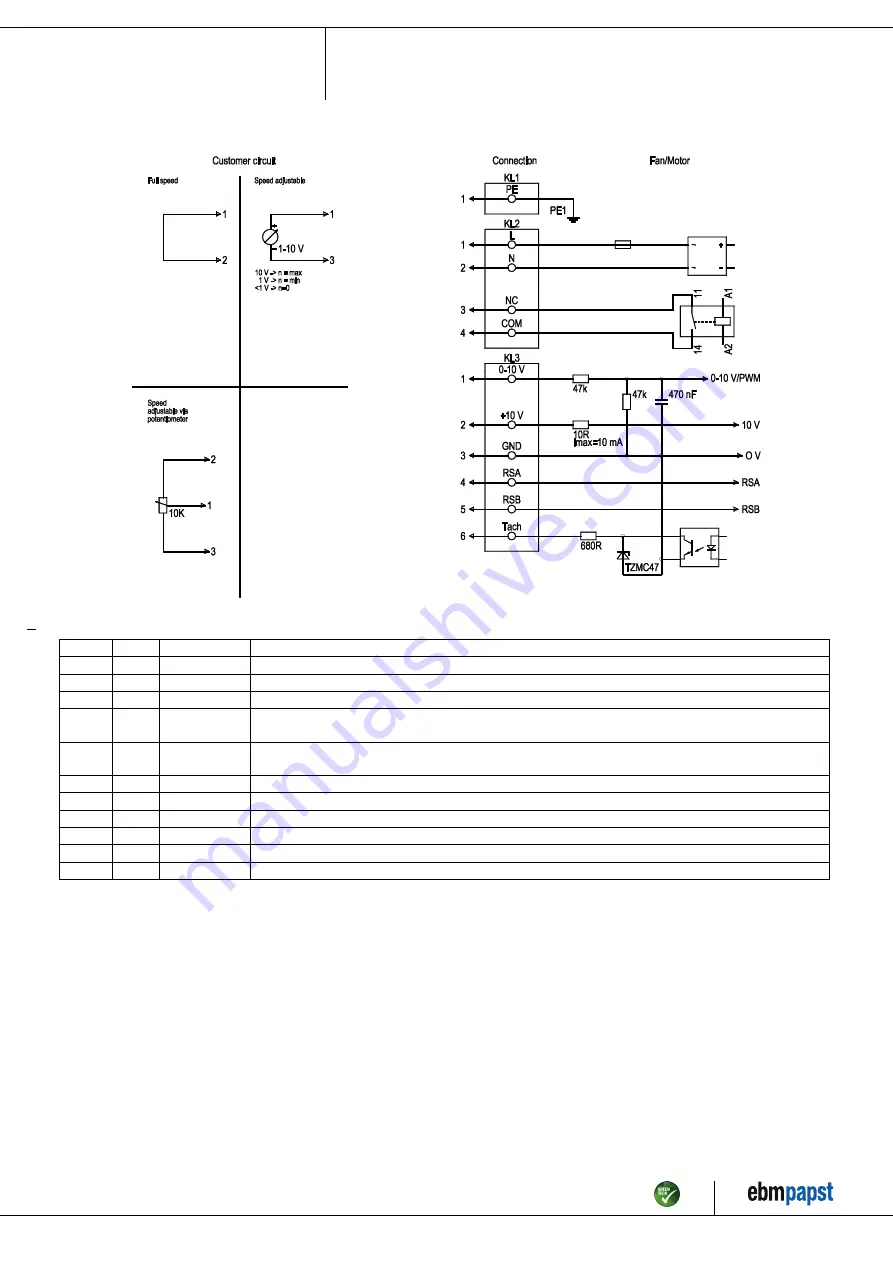
4.5 Connection diagram

Drawing preliminary!

No.

Conn.

Designation

Function/assignment

KL1

1

PE

Protective earth

KL2

1

L

Power supply, phase, 50/60 Hz

KL2

2

N

Power supply, neutral conductor, 50/60 Hz

KL2

3

NC

Status relay, floating status contact, break for failure, contact rating 250 VAC/2 A (AC1) min. 10 mA, basic
insulation on supply side and reinforced insulation on control interface side

KL2

4

COM

Status relay, floating status contact, common connection, contact rating 250 VAC / 2 A (AC1) / min. 10 mA;
basic insulation on supply side and reinforced insulation on control interface side

KL3

1

0-10 V

Analog input (set value), 0-10 V, Ri = 100 kΩ, adjustable curve, SELV

KL3

2

+10 V

Fixed voltage output 10 VDC, SELV

KL3

3

GND

Reference ground for control interface, SELV

KL3

4

RSA

RS485 interface for MODBUS, RSA; SELV

KL3

5

RSB

RS485 interface for MODBUS, RSB; SELV

KL3

6

Tacho

Tach output, open collector, 1 pulse per revolution, Isink max = 10 mA, SELV

Item no. 54390-5-9970 · ENU · Change 257332 · Approved 2022-09-08 · Page 9 / 12

ebm-papst Mulfingen GmbH & Co. KG · Bachmühle 2 · D-74673 Mulfingen · Phone +49 (0) 7938 81-0 · Fax +49 (0) 7938 81-110 · info1@de.ebmpapst.com · www.ebmpapst.com

Summary of Contents for D3G225-HE11-02

Page 1: ...staff Only authorized specialists are permitted to install the device to carry out a test run and to perform work on the electrical installation 1 3 Basic safety rules 1 1 3 Basic safety rules The sa...

Page 2: ...electromagnetic interference after installing the device in customer equipment Verify that the entire setup is EMC compliant 1 7 Mechanical movement DANGER Rotating device Risk of injury to body parts...

Page 3: ...n particular operating the device in the following ways is prohibited and could be hazardous Operating the device in an unbalanced state e g due to dirt deposits or ice formation Resonant operation op...

Page 4: ...10 V 3 3 GND 3 4 RSA 3 5 RSB 3 6 Tach 4 Tightening torque 3 0 5 Nm 5 Cable diameter min 6 mm max 10 mm tightening torque 1 8 0 3 Nm Cable diameter min 8 mm max 12 mm tightening torque 1 8 0 3 Nm seal...

Page 5: ...ies are used on the installation side the ebm papst evaluation loses its validity the conformity must be confirmed again The product does not fall within the scope of Regulation EU 2019 1781 due to th...

Page 6: ...ing hazard when removing blower from packaging Carefully remove the blower from its packaging touching only the housing Strictly avoid shocks Wear safety shoes and cut resistant safety gloves CAUTION...

Page 7: ...his operating state operational readiness is typically 4 W 4 2 3 Residual current circuit breaker RCCB If the use of a residual current device RCD is required in your installation only AC DC sensitive...

Page 8: ...parameter set 1 PWM control Mode parameter set 2 PWM control Fan device address 1 Max PWM 100 Min PWM 10 Save set value to EEPROM No Set value requirement Analog linear Direction of action parameter...

Page 9: ...contact common connection contact rating 250 VAC 2 A AC1 min 10 mA basic insulation on supply side and reinforced insulation on control interface side KL3 1 0 10 V Analog input set value 0 10 V Ri 10...

Page 10: ...emature failure 4 8 Switching off the device Switching off the device during operation Switch off the device via the control input Do not switch the motor e g in cyclic operation on and off via power...

Page 11: ...d rectify cause of error release restart lockout if necessary Ambient temperature too high Reduce the ambient temperature Reset by reducing control input to 0 Impermissible point of operation Correct...

Page 12: ...equirements NOTE Country specific legal requirements Always observe the applicable country specific legal regulations with regard to the disposal of products or waste occurring in the various phases o...

Reviews: