background image

Operating instructions

D3G318-AA35-01

Translation of the original operating instructions

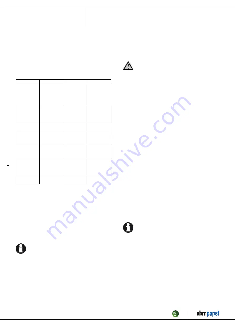
6.2 Safety inspection

NOTE
High-voltage test

The integrated EMC filter has Y capacitors. The tripping current
is exceeded when AC testing voltage is applied.
→ Test the device with DC voltage when you perform the

legally required high-voltage test. The voltage to be used
corresponds to the peak value of the AC voltage required by
the standard.

What to check

How to check

How often

What action?

Contact
protection
cover for
intactness or
damage

Visual inspection At least every

6 months

Repair or
replacement of
device

Device for
damage to
blades and
housing

Visual inspection At least every

6 months

Replacement of
device

Fastening the
cables

Visual inspection At least every

6 months

Fasten

Fastening the
protective earth
terminal

Visual inspection At least every

6 months

Fasten

Insulation of
cables for
damage

Visual inspection At least every

6 months

Replace cables

Impeller for
wear/deposits/
corrosion and
damage

Visual inspection At least every

6 months

Clean impeller
or replace device

Abnormal
bearing noise

acoustic

At least every
6 months

Replace device

6.3 Disposal

For ebm-papst, environmental protection and resource preservation are
top priority corporate goals.
ebm-papst operates an environmental management system which is
certified in accordance with ISO 14001 and rigorously implemented
around the world on the basis of German standards.
Right from the development stage, ecological design, technical safety
and health protection are fixed criteria.
The following section contains recommendations for ecological disposal
of the product and its components.

6.3.1 Country-specific legal requirements

NOTE
Country-specific legal requirements

Always observe the applicable country-specific legal
regulations with regard to the disposal of products or waste
occurring in the various phases of the life cycle. The
corresponding disposal standards are also to be heeded.

6.3.2 Disassembly

Disassembly of the product must be performed or supervised by
qualified personnel with the appropriate technical knowledge.
The product is to be disassembled into suitable components for disposal
employing standard procedures for motors.

WARNING
Heavy parts of the product may drop off. Some of the
product components are heavy. These components
could drop off during disassembly.

This can result in fatal or serious injury and material damage.
→ Secure components before unfastening to stop them falling.

6.3.3 Component disposal

The products are mostly made of steel, copper, aluminum and plastic.
Metallic materials are generally considered to be fully recyclable.
Separate the components for recycling into the following categories:

Steel and iron

Aluminum

Non-ferrous metal, e.g. motor windings

Plastics, particularly with brominated flame retardants, in accordance
with marking

Insulating materials

Cables and wires

Electronic scrap, e.g. circuit boards

Only ferrite magnets and not rare earth magnets are used in external
rotor motors from ebm-papst Mulfingen GmbH & Co. KG.

;

Ferrite magnets can be disposed of in the same way as normal iron
and steel.

Electrical insulating materials on the product, in cables and wires are
made of similar materials and are therefore to be treated in the same
manner.
The materials concerned are as follows:

Miscellaneous insulators used in the terminal box

Power cables

Cables for internal wiring

Electrolytic capacitors

Dispose of electronic components employing the proper procedures for
electronic scrap.

→ Please contact ebm-papst for any other questions on disposal.

Item no. 50384-5-9970 · ENU · Change 210923 · Approved 2020-03-14 · Page 11 / 11

ebm-papst Mulfingen GmbH & Co. KG · Bachmühle 2 · D-74673 Mulfingen · Phone +49 (0) 7938 81-0 · Fax +49 (0) 7938 81-110 · info1@de.ebmpapst.com · www.ebmpapst.com

Summary of Contents for D3G318-AA35-01

Page 1: ...y authorized specialists are permitted to install the device to carry out a test run and to perform work on the electrical installation 1 3 Basic safety rules 1 1 3 Basic safety rules The safety hazards associated with the device must be assessed again following installation in the final product The locally applicable industrial safety regulations are always to be observed when working on the devi...

Page 2: ...mpliant 1 7 Mechanical movement DANGER Rotating device Risk of injury to body parts coming into contact with the rotor or the impeller Secure the device against accidental contact Before working on the system machine wait until all parts have come to a standstill DANGER Ejected parts Missing protective devices may cause balancing weights or broken fan blades to be ejected and cause injuries Take a...

Page 3: ...structions Improper use In particular operating the device in the following ways is prohibited and could be hazardous Operating the device in an unbalanced state e g due to dirt deposits or ice formation Resonant operation operation with severe vibration This also includes vibration transmitted to the fan from the customer installation Operation in medical equipment with a life sustaining or life ...

Page 4: ...mm Cable length measured from electronics housing 800 20 mm 1 Cable PVC AWG18 6x crimped ferrules 2 Cable PVC AWG22 3x crimped ferrules Item no 50384 5 9970 ENU Change 210923 Approved 2020 03 14 Page 4 11 ebm papst Mulfingen GmbH Co KG Bachmühle 2 D 74673 Mulfingen Phone 49 0 7938 81 0 Fax 49 0 7938 81 110 info1 de ebmpapst com www ebmpapst com ...

Page 5: ...t optimum efficiency level The ErP data is determined using a motor impeller combination in a standardized measurement setup 3 4 Technical description Weight 21 4 kg Size 318 mm Motor size 112 Rotor surface Painted black Electronics housing material Die cast aluminum Impeller material Sheet steel galvanized Housing material Sheet steel galvanized Motor suspension Motor mounted on brackets for one ...

Page 6: ...vice is only connected to a connection point with a Ssc value that is greater than or equal to 120 times the rated output of the arrangement 4 CONNECTION AND STARTUP 4 1 Mechanical connection CAUTION Cutting and crushing hazard when removing blower from packaging Carefully remove the blower from its packaging touching only the housing Strictly avoid shocks Wear safety shoes and cut resistant safet...

Page 7: ...20 A C20A 2 5 14 3 PE AC 380 480 VAC 25 A 25 A C25A 4 0 12 AWG American Wire Gauge 4 2 3 Reactive currents Because of the EMC filter integrated for compliance with EMC limits interference emission and immunity to interference reactive currents can be measured in the supply line even when the motor is at a standstill and the line voltage is switched on The values are typically in the range 250 mA A...

Page 8: ...250 VAC min 10 mA AC1 1 7 NC white 2 Floating status contact break for failure 2 8 0 10 V yellow Control input set value 0 10 VDC impedance 100 kOhm SELV 2 11 10 V red Voltage output 10 VDC 3 max 10 mA power supply for external devices e g potentiometers SELV 2 12 GND blue Reference ground for control interface SELV Item no 50384 5 9970 ENU Change 210923 Approved 2020 03 14 Page 8 11 ebm papst Mul...

Page 9: ...e power supply When disconnecting be sure to disconnect the ground connection last 5 INTEGRATED PROTECTIVE FEATURES The integrated protective functions cause the motor to switch off automatically in the event of the faults described in the table Fault Safety feature description function Rotor position detection error An automatic restart follows Blocked rotor After the blockage is removed the moto...

Page 10: ...eaning To ensure a long service life check the fans regularly for proper operation and soiling The frequency of checking is to be adapted accordingly depending on the degree of soiling DANGER Risk of injury from rotating fan Only clean when not in motion Do not disconnect the fan from the power supply just switch it off via the control input This will prevent start up of the fan Dirt deposits on t...

Page 11: ...gal regulations with regard to the disposal of products or waste occurring in the various phases of the life cycle The corresponding disposal standards are also to be heeded 6 3 2 Disassembly Disassembly of the product must be performed or supervised by qualified personnel with the appropriate technical knowledge The product is to be disassembled into suitable components for disposal employing sta...

Reviews: