Operating instructions
G3G190-RD45-05
Translation of the original operating instructions
3.5 Mounting data
Any further mounting data required can be taken from the product
drawing or Section Chapter 4.1 Mechanical connection.
Strength class of
screws
8.8
For screw clearance, see Chapter 3.1 Product drawing
;
Secure the screws against unintentional loosening (e.g. use self-
locking screws).
3.6 Transport and storage conditions
Max. permitted
ambient temp. for
motor (transport/
storage)
+ 80 °C
Min. permitted
ambient temp. for
motor (transport/
storage)
- 40 °C
3.7 Electromagnetic compatibility
EMC immunity to
interference
According to EN 61000-6-2 (industrial
environment)
EMC circuit feedback
According to EN 61000-3-2/3
EMC interference
emission
According to EN 61000-6-3 (household
environment)
4. CONNECTION AND STARTUP
4.1 Mechanical connection
CAUTION
Cutting and crushing hazard when removing blower
from packaging
→ Carefully remove the blower from its packaging, touching
only the housing. Strictly avoid shocks.
→ Wear safety shoes and cut-resistant safety gloves.
;
Check the device for transport damage. Damaged devices are not to
be installed.
;
Install the undamaged device in accordance with your application.
4.1.1 Installing the fan
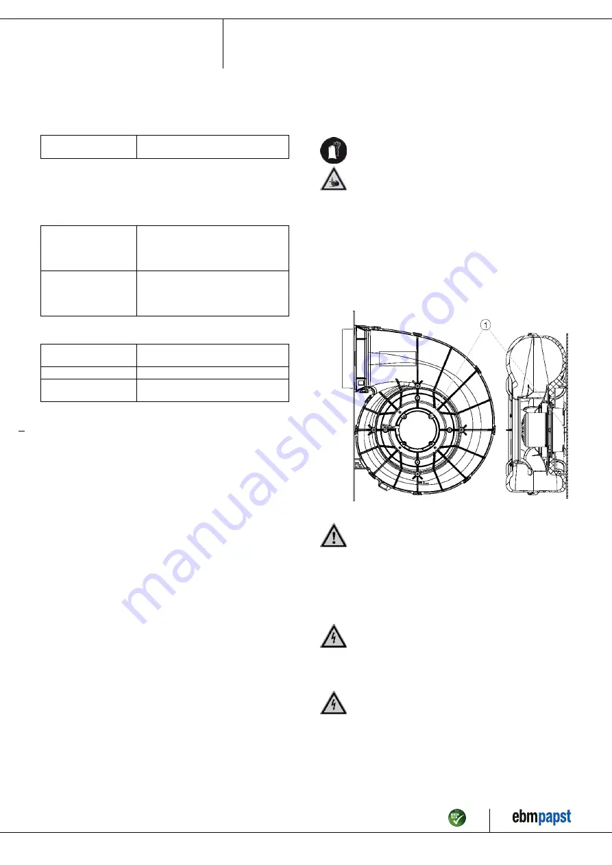
Attach the fan to the contact surfaces intended for this purpose. The air
must be able to circulate freely in the area of the electronics (1), adequate
ventilation must be ensured. The electronics (1) must not be covered up.
Fig. 1: Installed fan
CAUTION
Possible damage to the device
If the device slips during installation, serious damage can result.
→ Ensure that the device is securely positioned at its place of
installation until all fastening screws have been tightened.
●
The fan must not be strained on fastening.
4.2 Electrical connection
DANGER
Voltage on the device
Electric shock
→ Always connect a protective earth first.
→ Check the protective earth.
DANGER
Faulty insulation
Risk of fatal injury from electric shock
→ Use only cables that meet the specified installation
regulations for voltage, current, insulation material, capacity,
etc.
→ Route cables so that they cannot be touched by any
rotating parts.
Item no. 56679-5-9970 · ENU · Change 213950 · Approved 2021-11-19 · Page 6 / 11
ebm-papst Mulfingen GmbH & Co. KG · Bachmühle 2 · D-74673 Mulfingen · Phone +49 (0) 7938 81-0 · Fax +49 (0) 7938 81-110 · info1@de.ebmpapst.com · www.ebmpapst.com


