background image

Operating instructions

G3G190-RD45-05

Translation of the original operating instructions

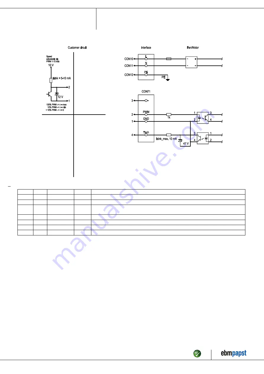
4.4 Connection diagram

Drawing preliminary!

No.

Conn.

Designation

Color

Function/assignment

CON10 L

black

Power supply, phase, see nameplate for voltage range

CON11 N

blue

Power supply, neutral conductor, see nameplate for voltage range

CON12 PE

green/
yellow

Protective earth

CON71

3

leer

not used

CON71

2

PWM

yellow

PWM, impedance 1 kΩ; SELV

CON71

4

Tacho

white

Tach output: open collector, 1 pulse per revolution, Isink max = 10 mA, SELV

CON71

1

GND

blue

Reference ground for control interface, SELV

Item no. 56679-5-9970 · ENU · Change 213950 · Approved 2021-11-19 · Page 8 / 11

ebm-papst Mulfingen GmbH & Co. KG · Bachmühle 2 · D-74673 Mulfingen · Phone +49 (0) 7938 81-0 · Fax +49 (0) 7938 81-110 · info1@de.ebmpapst.com · www.ebmpapst.com

Summary of Contents for G3G190-RD45-05

Page 1: ...nly authorized specialists are permitted to install the device to carry out a test run and to perform work on the electrical installation 1 3 Basic safety rules 1 1 3 Basic safety rules The safety haz...

Page 2: ...y that the entire setup is EMC compliant 1 7 Mechanical movement DANGER Rotating device Risk of injury to body parts coming into contact with the rotor or the impeller Secure the device against accide...

Page 3: ...prohibited and could be hazardous Operating the device in an unbalanced state e g due to dirt deposits or ice formation Resonant operation operation with severe vibration This also includes vibration...

Page 4: ...ew max 15 mm The torque is to be determined on the basis of the screw 4 5x sheet metal nut for thread EN ISO 1478 ST4 8 max screw length 16 mm plus thickness of mounting material 5 Screw on domes are...

Page 5: ...the conformity must be confirmed again The product does not fall within the scope of Regulation EU 2019 1781 due to the exception specified in Article 2 2a motors completely integrated into a product...

Page 6: ...ice for transport damage Damaged devices are not to be installed Install the undamaged device in accordance with your application 4 1 1 Installing the fan Attach the fan to the contact surfaces intend...

Page 7: ...earth connection circuit must be verified in the end application Depending on the installation situation it may be necessary to connect an additional protective earth conductor by way of the extra pr...

Page 8: ...ameplate for voltage range CON12 PE green yellow Protective earth CON71 3 leer not used CON71 2 PWM yellow PWM impedance 1 k SELV CON71 4 Tacho white Tach output open collector 1 pulse per revolution...

Page 9: ...e g in cyclic operation on and off via power supply Disconnect the device from the power supply When disconnecting be sure to disconnect the ground connection last 5 INTEGRATED PROTECTIVE FEATURES Th...

Page 10: ...necessary after that period contact ebm papst Adapt the maintenance intervals to the actual level of dust exposure 6 2 Safety inspection NOTE High voltage test The integrated EMC filter has Y capacito...

Page 11: ...lating materials Cables and wires Electronic scrap e g circuit boards Only ferrite magnets and not rare earth magnets are used in external rotor motors from ebm papst Mulfingen GmbH Co KG Ferrite magn...

Reviews: