background image

Operating instructions

K3G250-AV29-B2

Translation of the original operating instructions

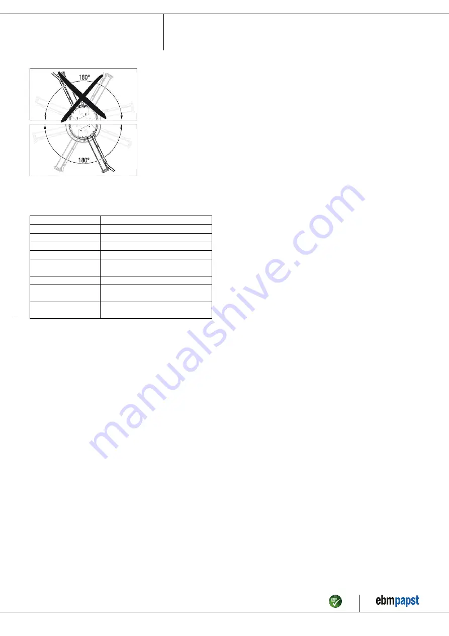
Fig. 4: Cable routing for fans installed upright.

4.4 Factory settings

Factory settings made for the device by ebm-papst.

Mode parameter set 1

PWM control

Mode parameter set 2

PWM control

Fan/device address

01

Max. PWM / %

100

Min. PWM / %

8,0

Save set value to
EEPROM

No

Set value requirement

Analog (linear)

Direction of action
parameter set 1

Positive (heating)

Direction of action
parameter set 2

Positive (heating)

Item no. 50679-5-9970 · ENU · Change 213957 · Approved 2020-07-14 · Page 9 / 13

ebm-papst Mulfingen GmbH & Co. KG · Bachmühle 2 · D-74673 Mulfingen · Phone +49 (0) 7938 81-0 · Fax +49 (0) 7938 81-110 · info1@de.ebmpapst.com · www.ebmpapst.com

Summary of Contents for K3G250-AV29-B2

Page 1: ...permitted to install the device to carry out a test run and to perform work on the electrical installation 1 3 Basic safety rules 1 1 3 Basic safety rules The safety hazards associated with the devic...

Page 2: ...t DANGER Rotating device Risk of injury to body parts coming into contact with the rotor or the impeller Secure the device against accidental contact Before working on the system machine wait until al...

Page 3: ...be hazardous Operating the device in an unbalanced state e g due to dirt deposits or ice formation Resonant operation operation with severe vibration This also includes vibration transmitted to the fa...

Page 4: ...Cable diameter min 4 mm max 10 mm tightening torque 2 5 0 4 Nm 2 Inlet ring with pressure tap k factor 70 3 Tightening torque 3 5 0 5 Nm Item no 50679 5 9970 ENU Change 213957 Approved 2020 07 14 Pag...

Page 5: ...imum efficiency level The ErP data is determined using a motor impeller combination in a standardized measurement setup 3 4 Technical description Weight 10 1 kg Size 250 mm Motor size 84 Rotor surface...

Page 6: ...g Carefully remove the device from the packaging by grasping hold of the frame Never subject to any impact Wear safety shoes and cut resistant safety gloves CAUTION Heavy load when unpacking device Ri...

Page 7: ...l to or greater than that of the phase conductor We recommend the use of 105 C cables Ensure that the minimum cable cross section is at least AWG 26 0 13 mm Protective earth contact resistance accordi...

Page 8: ...cope of delivery into the terminal box Connect the wires to the corresponding terminals Use a screwdriver to do so When connecting ensure that no wire ends fan out Fig 3 Connecting wires to terminals...

Page 9: ...eter set 2 PWM control Fan device address 01 Max PWM 100 Min PWM 8 0 Save set value to EEPROM No Set value requirement Analog linear Direction of action parameter set 1 Positive heating Direction of a...

Page 10: ...tion level KL3 2 8 GND Reference ground for control interface SELV KL3 3 7 0 10 V Control current sensor value input 0 10 VDC impedance 100 k use only as alternative to 4 20 mA input SELV KL3 4 10 V V...

Page 11: ...device for maintenance Switch off the device via the control input Do not switch the motor e g in cyclic operation on and off via power supply Disconnect the device from the power supply 5 INTEGRATED...

Page 12: ...n that will shorten the service life of the fan Severe vibration can destroy the fan In such cases switch off the fan immediately and clean it The preferred method of cleaning is dry cleaning e g usin...

Page 13: ...mbly of the product must be performed or supervised by qualified personnel with the appropriate technical knowledge The product is to be disassembled into suitable components for disposal employing st...

Reviews: