
Operating instructions
K3G280-AU11-C2
Translation of the original operating instructions
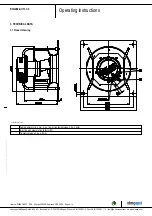
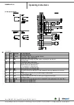
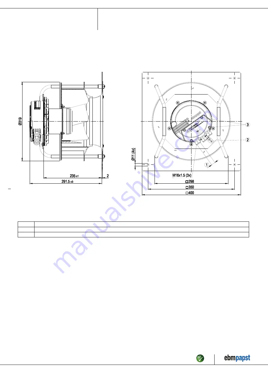
3. TECHNICAL DATA
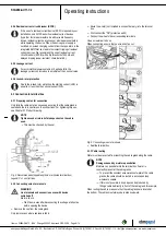
3.1 Product drawing
All dimensions in mm.
1
Cable diameter min. 4 mm, max. 10 mm; tightening torque 2.5 ± 0.4 Nm
2
Inlet ring with pressure tap (k-factor 93)
3
Tightening torque 3.5 ± 0.5 Nm
Item no. 50894-5-9970 · ENU · Change 202992 · Approved 2019-03-28 · Page 4 / 14
ebm-papst Mulfingen GmbH & Co. KG · Bachmühle 2 · D-74673 Mulfingen · Phone +49 (0) 7938 81-0 · Fax +49 (0) 7938 81-110 · info1@de.ebmpapst.com · www.ebmpapst.com


