
Operating instructions
K3G280-AU11-C2
Translation of the original operating instructions
With regard to cyclic speed loads, note that the rotating parts of
the device are designed for a maximum of one million load
cycles. If you have special questions, consult ebm-papst for
support.
;
Use the device in accordance with its degree of protection.
Information on surface quality
The surfaces of the products conform to the generally applicable industrial
standard. The surface quality may change during the production period.
This has no effect on strength, dimensional stability and dimensional
accuracy.
The color pigments in the paints used perceptibly react to UV light over
the course of time. This does not however in any way affect the
technical properties of the products. The product is to be protected against
UV radiation to prevent the formation of patches and fading. Changes in
color are not a reason for complaint and are not covered by the warranty.
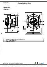
3.5 Mounting data
Strength class of
screws
8.8
;
Secure the screws against unintentional loosening (e.g. use self-
locking screws).
Any further mounting data required can be taken from the product
drawing or Section Chapter 4.1 Mechanical connection.
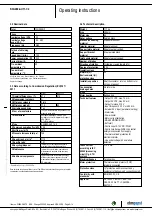
3.6 Transport and storage conditions
Max. permitted
ambient temp. for
motor (transport/
storage)
+80 °C
Min. permitted
ambient temp. for
motor (transport/
storage)
-40 °C
3.7 Electromagnetic compatibility
If several devices are switched in parallel on the supply side
so that the line current of the arrangement is in the range of 16-
75 A, then this arrangement conforms to IEC 61000-3-12
provided that the short-circuit power S
sc
at the connection point
of the customer system to the public power system is greater
than or equal to 120 times the rated output of the arrangement.
It is the responsibility of the installation engineer or operator/
owner of the device to ensure, if necessary after consultation
with the network operator, that this device is only connected to
a connection point with a S
sc
value that is greater than or equal
to 120 times the rated output of the arrangement.
4. CONNECTION AND STARTUP
4.1 Mechanical connection
CAUTION
Risk of cutting and crushing when removing device
from packaging
→ Carefully remove the device from the packaging by grasping
hold of the frame. Never subject to any impact.
→ Wear safety shoes and cut-resistant safety gloves.
CAUTION
Heavy load when unpacking device
Risk of physical injury, such as back injuries.
→ Two people should work together to remove the device from
its packaging.
NOTE
Damage to the device from vibration
Bearing damage, shorter service life
→ The fan must not be subjected to force or excessive vibration
from sections of the installation.
→ If the fan is connected to air ducts, the connection should
be isolated from vibration, e.g. using compensators or similar
elements.
→ Ensure stress-free attachment of the fan to the
substructure.
;
The fan may not be handled in the area around the inlet nozzle during
transport and installation.
There is a risk of damage to the impeller.
;
Check the device for transport damage. Damaged devices are not to
be installed.
;
Install the undamaged device in accordance with your application.
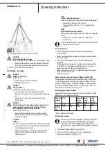
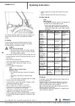
4.1.1 Installation of RadiPac fan
Use is always to be made of appropriate hoisting equipment and a
suiting lifting device when transporting the RadiPac for installation
purposes. Only suitable round slings are to be used for this purpose (see
Section 4.4 Technical Description for weight of product). Use four round
slings passed around the struts for lashing purposes. Position the round
slings as shown in the hoisting diagram below. Make sure that the struts
of the support bracket on the left and right of the motor are vertical.
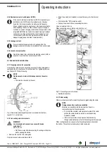
Transport the centrifugal fan in installation position as shown in the
product drawing. Heed the information given on the device! During
transportation, an acceleration of 2 g must not be exceeded.
Item no. 50894-5-9970 · ENU · Change 202992 · Approved 2019-03-28 · Page 6 / 14
ebm-papst Mulfingen GmbH & Co. KG · Bachmühle 2 · D-74673 Mulfingen · Phone +49 (0) 7938 81-0 · Fax +49 (0) 7938 81-110 · info1@de.ebmpapst.com · www.ebmpapst.com


