
Operating instructions
K3G280-AU11-C2
Translation of the original operating instructions
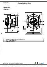
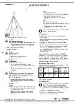
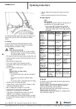
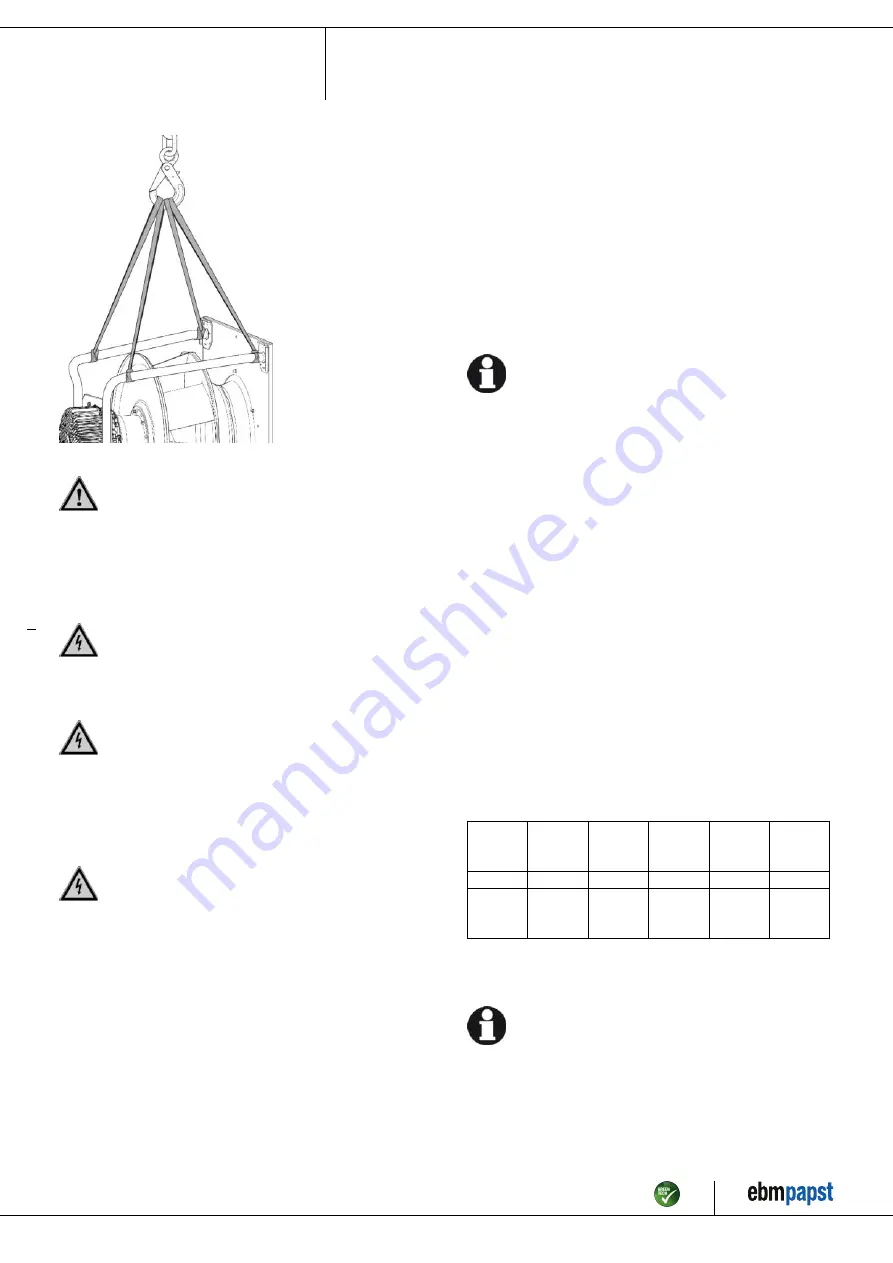
Fig. 1: Hoisting diagram for transportation of RadiPac
CAUTION
Possible damage to the device
If the device slips during installation, serious damage can result.
→ Ensure that the device is securely positioned at its place of
installation until all fastening screws have been tightened.
●
The fan must not be strained on fastening.
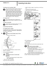
4.2 Electrical connection
DANGER
Voltage on the device
Electric shock
→ Always connect a protective earth first.
→ Check the protective earth.
DANGER
Faulty insulation
Risk of fatal injury from electric shock
→ Use only cables that meet the specified installation
regulations for voltage, current, insulation material, capacity,
etc.
→ Route cables so that they cannot be touched by any
rotating parts.
DANGER
Electrical charge (>50 µC) between phase conductor and
protective earth connection after switching off supply
with multiple devices connected in parallel.
Electric shock, risk of injury
→ Ensure sufficient protection against accidental contact.
Before working on the electrical hookup, short the supply
and PE connections.
CAUTION
Voltage
The fan is a built-in component and has no disconnecting switch.
→ Only connect the fan to circuits that can be switched off with
an all-pole disconnection switch.
→ When working on the fan, secure the system/machine in
which the fan is installed so as to prevent it from being
switched back on.
NOTE
Device malfunctions possible
Route the device's control lines separately from the supply line.
→ Maintain the greatest possible clearance.
Recommendation: clearance > 10 cm (separate cable
routing)
NOTE
Water ingress into wires or cables
Water ingress at the customer end of the cable can damage the
device.
→ Make sure the end of the cable is connected in a dry
environment.
Only connect the device to circuits that can be switched off with
an all-pole disconnection switch.
4.2.1 Requirements
;
Check whether the information on the nameplate matches the
connection data.
;
Before connecting the device, make sure the power supply matches
the device voltage.
;
Only use cables designed for the current level indicated on the
nameplate.
For determining the cross-section, note the sizing criteria according
to EN 61800-5-1. The protective earth must have a cross-section
equal to or greater than that of the phase conductor.
We recommend the use of 105 °C cables. Ensure that the minimum
cable cross-section is at least
AWG 26 / 0.13 mm².
Protective earth contact resistance according to EN 61800-5-1
Compliance with the resistance specifications according to EN 61800-5-
1 for the protective earth connection circuit must be verified in the end
application. Depending on the installation situation, it may be necessary
to connect an additional protective earth conductor by way of the extra
protective earth terminal provided on the device.
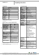
4.2.2 Supply connection and fuses
Assignment of supply cable cross-sections and their required fuses (line
protection only, no equipment protection).
Nominal
voltage
Fuse
Automatic
circuit
breaker
Cable
cross-
section
Cable
cross-
section
VDE
UL
VDE
mm²
*AWG
3/PE AC
380-480
VAC
16 A
15 A
C16A
1.5
2.5
16
* AWG = American Wire Gauge
4.2.3 Reactive currents
Because of the EMC filter integrated for compliance with EMC
limits (interference emission and immunity to interference),
reactive currents can be measured in the supply line even
when the motor is at a standstill and the line voltage is switched
on.
●
The values are typically in the range < 250 mA
●
At the same time, the effective power in this operating state
(operational readiness) is typically < 5 W.
Item no. 50894-5-9970 · ENU · Change 202992 · Approved 2019-03-28 · Page 7 / 14
ebm-papst Mulfingen GmbH & Co. KG · Bachmühle 2 · D-74673 Mulfingen · Phone +49 (0) 7938 81-0 · Fax +49 (0) 7938 81-110 · info1@de.ebmpapst.com · www.ebmpapst.com


