background image

Operating instructions

K3G310-RS01-I2

Translation of the original operating instructions

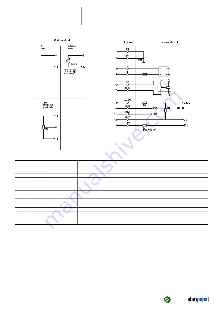
4.5 Connection diagram

Drawing preliminary!

No.

Conn.

Designation

Color

Function/assignment

1

1, 2

PE

green/
yellow

Protective earth

1

3

N

blue

Power supply, neutral conductor, 50/60 Hz

1

5

L

black

Power supply, phase, 50/60 Hz

1

6

NC

white 1

Status relay, floating status contact; break for failure, contact rating 250 VAC / 2A (AC1) / min. 10
mA, basic insulation on supply side and reinforced insulation on control interface side

1

7

COM

white 2

Status relay, floating status contact; common connection, contact rating 250 VAC / 2A (AC1) / min.
10 mA, basic insulation on supply side and reinforced insulation on control interface side

2

8

0-10V

yellow

Analog input (set value); 0-10 V; Ri = 100 kΩ; adjustable curve

2

10

RSB

brown

RS485 interface for MODBUS, RSB

2

11

RSA

white

RS485 interface for MODBUS, RSA

2

12

GND

blue

Reference ground for control interface, SELV

2

13

+10V

red

Fixed voltage output 10 VDC, +10 V ±3%; max. 10 mA; short-circuit-proof; power supply for
external devices (e.g. pot)

Item no. 52822-5-9970 · ENU · Change 212319 · Approved 2020-10-07 · Page 8 / 11

ebm-papst Mulfingen GmbH & Co. KG · Bachmühle 2 · D-74673 Mulfingen · Phone +49 (0) 7938 81-0 · Fax +49 (0) 7938 81-110 · info1@de.ebmpapst.com · www.ebmpapst.com

Summary of Contents for K3G310-RS01-I2

Page 1: ...ts are permitted to install the device to carry out a test run and to perform work on the electrical installation 1 3 Basic safety rules 1 1 3 Basic safety rules The safety hazards associated with the...

Page 2: ...ntact Before working on the system machine wait until all parts have come to a standstill WARNING Rotating device Long hair and dangling items of clothing jewelry and the like can become entangled and...

Page 3: ...Nominal data Operating the device with all protective devices Following the operating instructions Improper use In particular operating the device in the following ways is prohibited and could be haza...

Page 4: ...drawing All dimensions in mm 1 Cable PVC AWG18 5x crimped ferrules 2 Cable PVC AWG22 5x crimped ferrules Item no 52822 5 9970 ENU Change 212319 Approved 2020 10 07 Page 4 11 ebm papst Mulfingen GmbH...

Page 5: ...ion in a standardized measurement setup 3 4 Technical description Weight 10 7 kg Size 310 mm Motor size 84 Rotor surface Painted black Electronics housing material Die cast aluminum Impeller material...

Page 6: ...UP 4 1 Mechanical connection CAUTION Risk of cutting and crushing when removing device from packaging Carefully remove the device from the packaging by grasping hold of the frame Never subject to any...

Page 7: ...ol and a hole 4 2 2 Reactive currents Because of the EMC filter integrated for compliance with EMC limits interference emission and immunity to interference reactive currents can be measured in the su...

Page 8: ...relay floating status contact common connection contact rating 250 VAC 2A AC1 min 10 mA basic insulation on supply side and reinforced insulation on control interface side 2 8 0 10V yellow Analog inpu...

Page 9: ...e during operation Switch off the device via the control input Do not switch the motor e g in cyclic operation on and off via power supply Switching off the device for maintenance Switch off the devic...

Page 10: ...ong service life check the fans regularly for proper operation and soiling The frequency of checking is to be adapted accordingly depending on the degree of soiling DANGER Risk of injury from rotating...

Page 11: ...or ecological disposal of the product and its components 6 4 1 Country specific legal requirements NOTE Country specific legal requirements Always observe the applicable country specific legal regulat...

Reviews: