


Operating instructions
K3G355-BC92-02
Translation of the original operating instructions
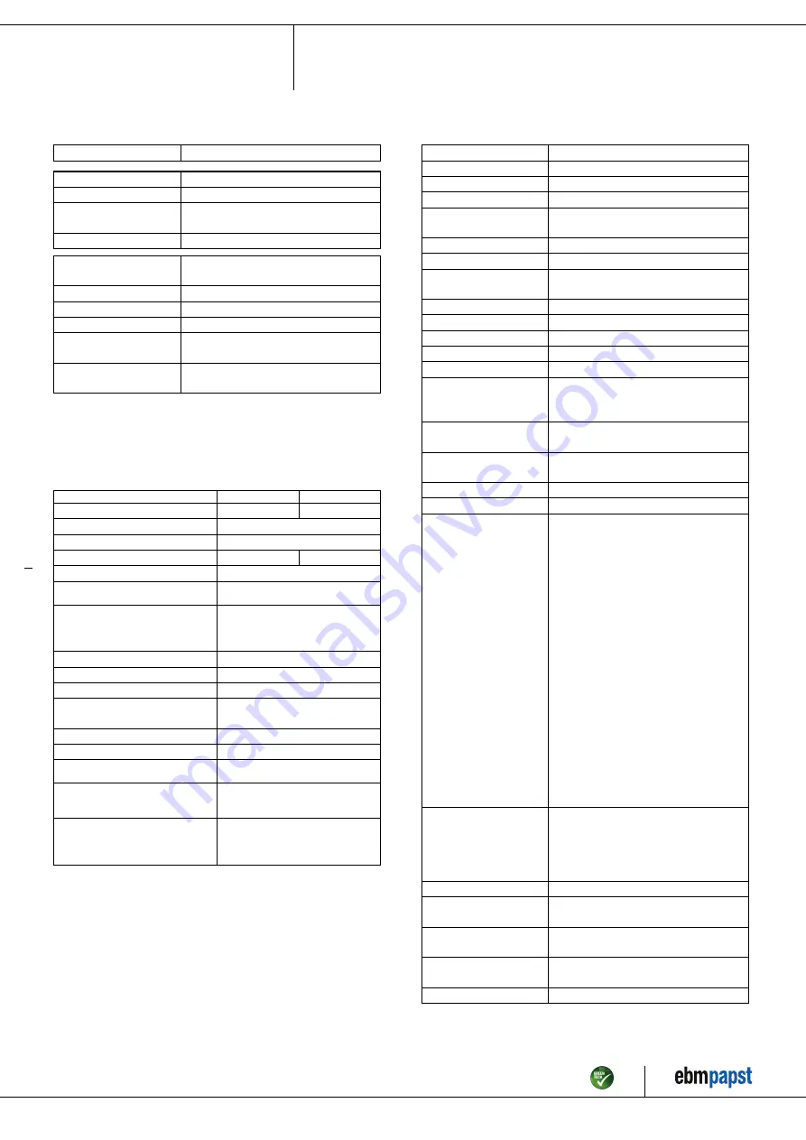
3.2 Nominal data
Motor
M3G112-IA
Phase
3~
Nominal voltage / VAC
400
Nominal voltage
range / VAC
380 .. 480
Frequency / Hz
50/60
Method of obtaining
data
ml
Speed (rpm) / min
-1
2800
Power consumption / W
2250
Current draw / A
3.5
Min. ambient
temperature / °C
-25
Max. ambient
temperature / °C
55
ml = Max. load · me = Max. efficiency · fa = Free air
cs = Customer specification · ce = Customer equipment
Subject to change
3.3 Data according to Commission Regulation (EU) 327/
2011
Actual
Req. 2015
01 Overall efficiency η
es
/ %
64.1
55.2
02 Measurement category
A
03 Efficiency category
Static
04 Efficiency grade N
70.9
62
05 Variable speed drive
Yes
06 Year of manufacture
The year of manufacture is specified on the
product's rating label.
07 Manufacturer
ebm-papst Mulfingen GmbH & Co. KG
Amtsgericht (court of registration) Stuttgart ·
HRA 590344
D-74673 Mulfingen
08 Type
K3G355-BC92-02
09 Power consumption P
ed
/ kW
2.24
09 Air flow q
v
/ m³/h
4680
09 Pressure increase total p
sf
/
Pa
1038
10 Speed (rpm) n / min
-1
2825
11 Specific ratio
*
1.01
12 Recycling/disposal
Information on recycling and disposal is
provided in the operating instructions.
13 Maintenance
Information on installation, operation and
maintenance is provided in the operating
instructions.
14 Additional components
Components used to calculate the energy
efficiency that are not apparent from the
measurement category are detailed in the
CE declaration.
*
Specific ratio = 1 + p
fs
/ 100 000 Pa
Data obtained at optimum efficiency level. The ErP data is determined using a motor-impeller
combination in a standardized measurement setup.
3.4 Technical description
Weight
26 kg
Size
355 mm
Motor size
112
Rotor surface
Painted black
Electronics housing
material
Die-cast aluminum
Impeller material
Sheet aluminum
Support plate material
Sheet steel, galvanized
Support bracket
material
Steel, painted black
Inlet nozzle material
Sheet steel, galvanized
Number of blades
7
Direction of rotation
Clockwise, viewed toward rotor
Degree of protection
IP54
Insulation class
"B"
Moisture (F) /
Environmental (H)
protection class
H1
Installation position
Shaft horizontal or rotor on bottom; rotor
on top on request
Condensation
drainage holes
On rotor side
Mode
S1
Motor bearing
Ball bearing
Technical features
- Output 10 VDC, max. 10 mA
- Output 20 VDC, max. 50 mA
- Output for slave 0-10 V
- Operation and alarm display
- Input for sensor 0-10 V or 4-20 mA
- External 24 V input (parameter setting)
- External release input
- Alarm relay
- Integrated PID controller
- Motor current limitation
- PFC, passive
- RS-485 MODBUS-RTU
- Soft start
- Control input 0-10 VDC / PWM
- Control interface with SELV potential
safely disconnected from supply
- Thermal overload protection for
electronics/motor
- Line undervoltage / phase failure
detection
Touch current
according to IEC
60990 (measuring
circuit Fig. 4, TN
system)
<= 3.5 mA
Electrical hookup
Terminal box
Motor protection
Thermal overload protector (TOP)
internally connected
Protection class
I (with customer connection of protective
earth)
Conformity with
standards
EN 61800-5-1; CE
Approval
EAC; UL 1004-7 + 60730-1
Item no. 52485-5-9970 · ENU · Change 212946 · Approved 2020-07-14 · Page 5 / 14
ebm-papst Mulfingen GmbH & Co. KG · Bachmühle 2 · D-74673 Mulfingen · Phone +49 (0) 7938 81-0 · Fax +49 (0) 7938 81-110 · info1@de.ebmpapst.com · www.ebmpapst.com


