background image

Operating instructions

K3G450-AQ24-01

Translation of the original operating instructions

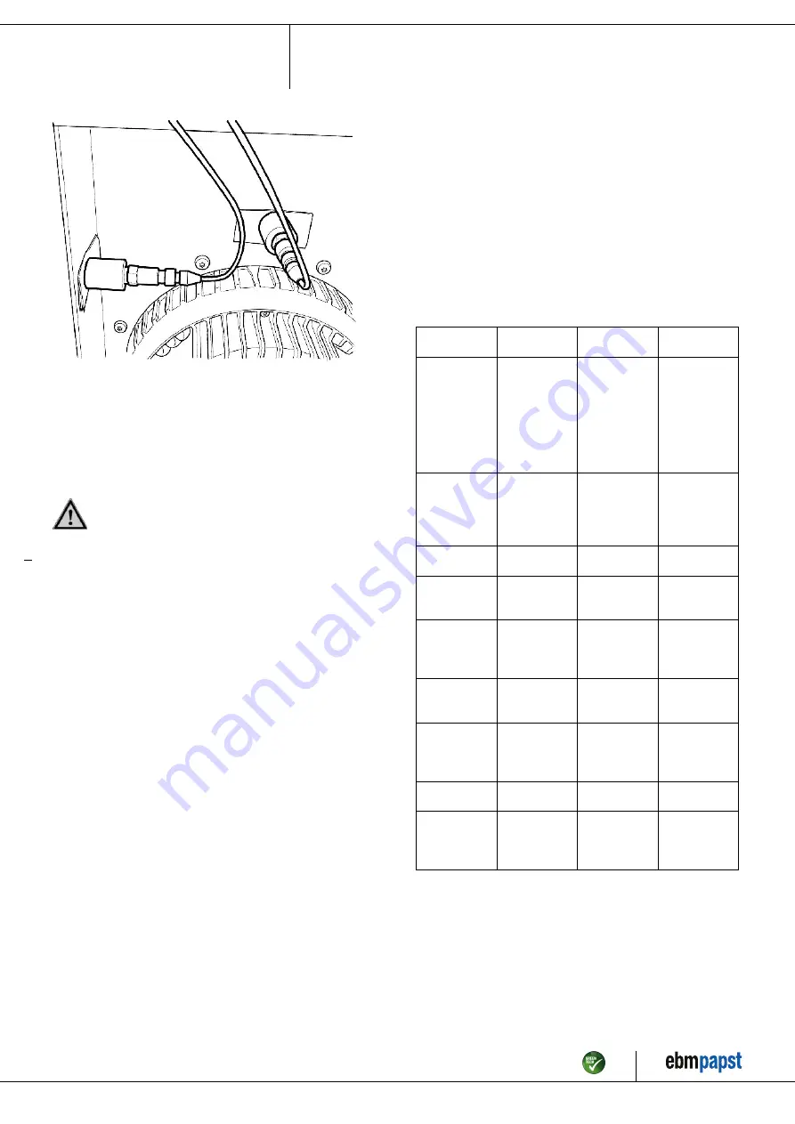
Fig. 4: Example showing vibration measurement. Positioning of the
sensors will vary depending on the device and the circumstances of
installation.

6.2 Cleaning

To ensure a long service life, the fans have to be regularly checked for
proper operation and degree of soiling. The frequency of the checks is to
be adapted to the occurrence of soiling.

DANGER
Risk of injury from rotating fan.

→ Only clean when not in motion. Do not disconnect the fan

from the power supply, just switch it off via the control input.
This will prevent start-up of the fan.

;

Dirt deposits on the motor housing could lead to overheating of the
motor.

;

Dirt on the impeller can cause vibration which would shorten the
service life of the fan.

;

Severe vibration could destroy the fan.

;

In such cases immediately switch off and clean the fan.

;

The preferred method of cleaning is dry cleaning, e.g. using
compressed air.

;

Use is never to be made of corrosive cleaning agents!

NOTE
Damage to the device during cleaning

Malfunction possible
→ Do not use a high-pressure cleaner to clean the device.# Do

not use any acid, alkali or solvent-based cleaning agents.

→ Do not use any pointed or sharp-edged objects for cleaning

;

Completely remove any cleaning agents used.

;

Immediately switch off and replace the device if severe corrosion is
apparent at load-bearing or rotating parts.

;

Repairs to load-bearing or rotating parts are not permissible!

;

Operate the fan for 2 hours at maximum speed to permit the
evaporation of any water which may have ingressed.

;

If cleaning does not eliminate vibration, the fan may have to be re-
balanced. In such cases please contact ebm-papst.

;

The fan is provided with maintenance-free ball bearings. The lifetime
lubrication of the ball bearings is designed for a service life of 40,000
hours.

;

Please contact ebm-papst if bearing replacement is required after this
period.

;

Adapt the maintenance intervals to the dust pollution occurring.

6.3 Safety test

NOTE
High-voltage test

The integrated EMC filter contains Y capacitors. Therefore, the
trigger current is exceeded when AC testing voltage is applied.
→ Test the device with DC voltage when you carry out the

high-voltage test required by law. The voltage to be used
corresponds to the peak value of the AC voltage required by
the standard.

What has to
be tested?

How to test?

Frequency

Which
measure?

Check the
protective
casing against
accidental
contact for
damage and to
ensure that it is
intact

Visual inspection At least every

6 months

Repair or
replacement of
the device

Check the
device for
damage to
blades and
housing

Visual inspection At least every

6 months

Replacement of
the device

Mounting the
connection lines

Visual inspection At least every

6 months

Fasten

Check the
insulation of the
wires for damage

Visual inspection At least every

6 months

Replace wires

Impeller for
wear/deposits/
corrosion and
damage

Visual inspection At least every

6 months

Clean impeller
or replace device

Tightness of
screwed cable
gland

Visual inspection At least every

6 months

Retighten,
replace if
damaged

Condensate
discharge holes
for clogging, as
necessary

Visual inspection At least every

6 months

Open bore holes

Abnormal
bearing noise

acoustic

At least every
6 months

Replace device

Vibration test

Vibration tester,
acceleration or
deceleration
measurement

Recommended
every 6 months

Clean impeller
or replace device

Item no. 50638-5-9970 · ENG · Revision 209539 · Release 2021-02-12 · Page 14 / 15

ebm-papst Mulfingen GmbH & Co. KG · Bachmühle 2 · D-74673 Mulfingen · Phone +49 (0) 7938 81-0 · Fax +49 (0) 7938 81-110 · info1@de.ebmpapst.com · www.ebmpapst.com

Summary of Contents for K3G450-AQ24-01

Page 1: ...rry out a test run and to perform work on the electrical installation 1 3 Basic safety rules 1 1 3 Basic safety rules Any safety hazards stemming from the device must be re evaluated once it is installed in the end device The local industrial safety regulations must always be observed when working on the device Keep the workplace clean and tidy Untidiness in the working area increases the risk of ...

Page 2: ...d Secure the device against accidental contact Before working on the system machine wait until all parts have come to a standstill DANGER Flying parts Missing safety devices may cause balancing weights or broken fan blades to be ejected at high speeds causing bodily harm Take appropriate safety measures WARNING Rotating device Long hair dangling items of clothing jewellery and similar items can be...

Page 3: ...er 3 2 Nominal data Operating the device with all protective features in place Minding the operating instructions Improper use Using the device in the following ways is particularly prohibited and may cause hazards Operating the device with an imbalance e g caused by dirt deposits or icing Resonance mode operation with heavy vibrations These also include vibrations that are transmitted from the cu...

Page 4: ...y vertically as shown in the view or rotor on bottom rotor on top on request 2 Cable diameter min 4 mm max 10 mm tightening torque 4 0 6 Nm 3 Inlet nozzle with pressure tap k factor 240 4 Tightening torque 3 5 0 5 Nm Item no 50638 5 9970 ENG Revision 209539 Release 2021 02 12 Page 4 15 ebm papst Mulfingen GmbH Co KG Bachmühle 2 D 74673 Mulfingen Phone 49 0 7938 81 0 Fax 49 0 7938 81 110 info1 de e...

Page 5: ...sed on the installation side the ebm papst evaluation loses its validity conformity must be confirmed again The product does not fall within the scope of Regulation EU 2019 1781 due to the exception specified in Article 2 2a motors completely integrated into a product 3 4 Technical features Mass 39 kg Size 450 mm Motor size 150 Surface of rotor Coated in black Material of electronics housing Die c...

Page 6: ...rator owner of the device to ensure if necessary after consultation with the network operator that this device is only connected to a connection point with a Ssc value that is greater than or equal to 120 times the rated output of the arrangement 4 CONNECTION AND START UP 4 1 Connecting the mechanical system CAUTION Cutting and crushing hazard when removing device from packaging Carefully remove t...

Page 7: ...into leads or wires Water enters at the cable end on the customers side and can damage the device Make sure that the cable end is connected in a dry environment Connect the device only to circuits that can be switched off using an all pole disconnecting switch 4 2 1 Prerequisites Check that the data on the type plate match the connection data Before connecting the device ensure that the supply vol...

Page 8: ...r protection Due to the locked rotor protection the start up current LRA is equal to or less than the nominal current FLA 4 3 Connection in terminal box 4 3 1 Preparing connection lines for the connection Strip the cable just enough so that the screwed cable gland is tight and the terminals are relieved of strain Tightening torque see chapter 3 1 Product drawing NOTE Tightness and strain relief de...

Page 9: ...rip edge can be produced by fitting a cable tie directly in front of the cable gland for example 4 4 Factory settings Factory settings with which the device is pre set by ebm papst Control mode parameter set 1 PWM controlling Control mode parameter set 2 PWM controlling Fan device adress 1 Max PWM 100 Min PWM 5 1 Save set value to EEPROM Yes Set value control Analogue linear Control function param...

Page 10: ...contact common connection contact rating 250 VAC max 2 A AC1 min 10 mA KL2 3 NC Status relay floating status contact break for failure KL 3 1 RSA Bus connection RS 485 RSA MODBUS RTU SELV KL 3 2 RSB Bus connection RS 485 RSB MODBUS RTU SELV KL 3 3 10 GND Signal ground for control interface SELV KL 3 4 Ain1 U Analogue input 1 set value 0 10 V Ri 100 kΩ parametrisable curve only usable as alternativ...

Page 11: ...OM setting the controller function of the integrated controller is normally inversely selectable per bus or per digital input Din 3 normal open pin or applied voltage 5 50 VDC inverse bridge to GND or applied voltage 1 VDC SELV KL 3 11 Ain2 U Analogue input 2 actual value 0 10 V Ri 100 kΩ parametrisable curve only usable as alternative to input Ain2 SELV KL 3 12 20 V Fixed voltage output 20 VDC 20...

Page 12: ...ance frequencies that may be present When regulating the speed pass through resonance ranges as quickly as possible or find another remedy Operation at excessive vibration levels can lead to premature failure The maximum vibration severity may not exceed 3 5 mm s and should be checked every 6 months It must be measured at least in and perpendicular to the axial direction at the place where the mot...

Page 13: ...ff de energise and remove mechanical blockage Mains supply voltage faulty Check mains supply voltage restore power supply Important The error message resets automatically The device starts up again automatically without advance warning Faulty connection De energise correct connection see connection diagram Motor winding broken Replace device Insufficient cooling Improve cooling Let the device cool...

Page 14: ...d with maintenance free ball bearings The lifetime lubrication of the ball bearings is designed for a service life of 40 000 hours Please contact ebm papst if bearing replacement is required after this period Adapt the maintenance intervals to the dust pollution occurring 6 3 Safety test NOTE High voltage test The integrated EMC filter contains Y capacitors Therefore the trigger current is exceede...

Page 15: ...nts could drop off during disassembly This can result in fatal or serious injury and material damage Secure components before unfastening to stop them falling 6 4 3 Component disposal The products are mostly made of steel copper aluminium and plastic Metallic materials are generally considered to be fully recyclable Separate the components for recycling into the following categories Steel and iron...

Reviews: