background image

Operating instructions

K3G500-PA23-71

Translation of the original operating instructions

4.6 Checking the connections

;

Make sure that the power is off (all phases).

;

Secure it from being switched on again.

;

Check the correct fit of the connection lines.

;

Screw the terminal box cover closed again. Terminal box tightening
torque, see chapter 3.1 Product drawing.

;

Route the connecting cables in the terminal box so that the terminal
box cover closes without resistance.

;

Use all plug screws (the entire number). In doing so, insert the
screws manually to avoid damage to the thread.

;

Make sure that the terminal box is correctly closed and sealed and
that all screws and screwed cable glands are properly tightened.

4.7 Switch on device

The device is not to be switched on until it has been installed properly
and in accordance with its intended use, including the required protective
devices and professional electrical connection. This also applies to
devices which have already been equipped with plugs and terminals or
similar connectors by the customer.

WARNING
Hot motor housing

Fire hazard
→ Ensure that no combustible or flammable materials are

located close to the fan.

;

Inspect the device for visible external damage and the proper function
of the protective features before switching it on.

;

Check the air flow paths of the fan for foreign objects and remove any
that are found.

;

Apply the nominal voltage to the voltage supply.

;

Start the device by changing the input signal.

NOTE
Damage to device by vibrations

Bearing damage, reduced service life
→ The fan must operate free of vibrations throughout its speed

control range. #Strong vibrations can result from improper
handling, imbalance resulting from damage during transport,
or component-induced or structural resonances. #When
putting the fan into service, determine the speed ranges with
excessive vibration levels and also any resonance
frequencies that may be present. #When regulating the
speed, pass through resonance ranges as quickly as
possible or find another remedy.# Operation at excessive
vibration levels can lead to premature failure.

4.8 Switching off the device

Switching off the device during operation:

;

Switch off the device via the control input.

;

Do not switch the motor (e.g. in cyclic operation) on and off via power
supply.

Switching off the device for maintenance work:

;

Switch off the device via the control input.

;

Do not switch the motor (e.g. in cyclic operation) on and off via power
supply.

;

Disconnect the device from the supply voltage.

;

When disconnecting, be sure to disconnect the earth wire connection
last.

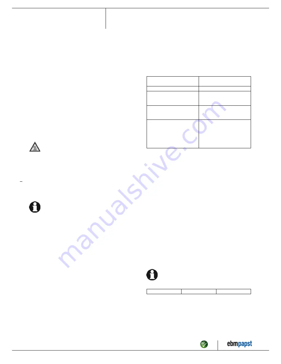
5. INTEGRATED PROTECTIVE FUNCTIONS

The integrated protective functions cause the motor to switch off
automatically in case of faults described in the table.

Malfunctions

Description / Function of
safety feature

Rotor position detection error

An automatic restart occurs.

Locked rotor

;

After the blockage is

removed, the motor restarts
automatically.

Line under-voltage (mains input
voltage outside of permitted
nominal voltage)

;

If the mains supply voltage

returns to permitted values, the
motor restarts automatically.

Phase failure

A phase of the supply voltage
fails for at least 5 s.

;

If all phases are correctly

supplied again, the motor
automatically restarts after 10 -
40 s.

6. MAINTENANCE, MALFUNCTIONS, POSSIBLE
CAUSES AND REMEDIES

Do not perform any repairs on your device. Return the device to ebm-
papst for repair or replacement.

WARNING
Terminals and connections have voltage even with a
unit that is shut off

Electric shock
→ Wait five minutes after disconnecting the voltage at all poles

before opening the device.

CAUTION
If control voltage is applied or a speed setpoint is stored,
the motor will restart automatically, e.g. after power
failure.

Risk of injury
→ Keep out of the device danger zone.# When working on the

device, switch off the mains power and ensure that it cannot
be switched back on.

→ After working on the device, remove any tools used or

other objects from the device.

If the device remains out of use for over four months, we
recommend switching the device on for at least three hours at
full speed to allow any condensate to evaporate and to move
the bearings.

Malfunction/error

Possible cause

Possible remedy

Item no. 54419-5-9970 · ENG · Revision 90170 · Release 2016-07-14 · Page 10 / 12

ebm-papst Mulfingen GmbH & Co. KG · Bachmühle 2 · D-74673 Mulfingen · Phone +49 (0) 7938 81-0 · Fax +49 (0) 7938 81-110 · info1@de.ebmpapst.com · www.ebmpapst.com

Summary of Contents for K3G500-PA23-71

Page 1: ...arry out a test run and to perform work on the electrical installation 1 3 Basic safety rules 1 1 3 Basic safety rules Any safety hazards stemming from the device must be re evaluated once it is installed in the end device Observe the following when working on the unit Do not make any modifications additions or conversions to the device without the approval of ebm papst 1 4 Electrical voltage 1 1 ...

Page 2: ...ave come to a standstill DANGER Flying parts Missing safety devices may cause balancing weights or broken fan blades to be ejected at high speeds causing bodily harm Take appropriate safety measures WARNING Rotating device Long hair dangling items of clothing jewellery and similar items can become entangled and be pulled into the device Risk of injury Do not wear any loose fitting or dangling clot...

Page 3: ...lowing ways is particularly prohibited and may cause hazards Operating the device with an imbalance e g caused by dirt deposits or icing Resonance mode operation with heavy vibrations These also include vibrations that are transmitted from the customer system to the fan Operation in medical equipment with a life sustaining or lifesaving function Operation with external vibrations Moving solids con...

Page 4: ...own in the illustration or rotor on bottom rotor on top on request 2 Cable diameter min 4 mm max 10 mm tightening torque 4 0 6 Nm 3 Tightening torque 3 5 0 5 Nm 4 Inlet nozzle with pressure tap k factor 281 5 Mounting holes for FlowGrid Item no 54419 5 9970 ENG Revision 90170 Release 2016 07 14 Page 4 12 ebm papst Mulfingen GmbH Co KG Bachmühle 2 D 74673 Mulfingen Phone 49 0 7938 81 0 Fax 49 0 793...

Page 5: ...tion with optimum efficiency The ErP data is determined using a motor impeller combination in a standardised measurement configuration 3 4 Technical features Mass 38 7 kg Size 500 mm Surface of rotor Coated in black Material of electronics housing Die cast aluminium Material of impeller Aluminium sheet Material of mounting plate Sheet steel galvanised Material of support bracket Steel coated in bl...

Page 6: ...at is greater than or equal to 120 times the rated output of the arrangement 4 CONNECTION AND START UP 4 1 Connecting the mechanical system CAUTION Cutting and crushing hazard when removing device from packaging Carefully remove the device from its packaging only touching the housing Strictly avoid shocks Wear safety shoes and cut resistant safety gloves CAUTION Device weighs more than 25 kg Heavy...

Page 7: ...terminal provided on the device The protective earth terminal is located on the housing and provided with a protective earth symbol and a hole 4 2 2 Power supply connection fuse protection Assignment of conductor cross sections and the fuse protection required for them overload protection only no device protection Nominal voltage Safety fuse Automatic circuit breaker Wire cross section Wire cross ...

Page 8: ...ith the seal inserts provided in the terminal box Insert the line s not included in the standard scope of delivery into the terminal box First connect the PE protective earth connection Connect the lines to the corresponding terminals Use a screwdriver to do so During the connection work ensure that no cables splice off Fig 2 Connecting the wires to terminals Seal the terminal box 4 3 3 Cable rout...

Page 9: ...on connection contact rating 250 VAC 2 A AC1 KL 2 5 Din1 Digital input 1 enabling of electronics enabling open pin or applied voltage 5 50 VDC disabling bridge to GND or applied voltage 1 VDC reset function triggers software reset after a level change to 1 V SELV KL 2 6 10 V Fixed voltage output 10 VDC 10 V 3 max 10 mA short circuit proof power supply for external devices e g potentiometer SELV Al...

Page 10: ... off the device Switching off the device during operation Switch off the device via the control input Do not switch the motor e g in cyclic operation on and off via power supply Switching off the device for maintenance work Switch off the device via the control input Do not switch the motor e g in cyclic operation on and off via power supply Disconnect the device from the supply voltage When disco...

Page 11: ...ernatively reset the error message by applying a control signal of 0 5 V to DIN1 or by short circuiting Din1 to GND Unacceptable operating point e g counterpressure is too high Correct the operating point Let the device cool down To reset the error message switch off the mains supply voltage for a min of 25 s and switch it on again Alternatively reset the error message by applying a control signal...

Page 12: ...ogical disposal of the product and its components 6 4 1 Country specific legal requirements NOTE Country specific legal requirements Always observe the applicable country specific legal regulations with regard to the disposal of products or waste occurring in the various phases of the life cycle The corresponding disposal standards are also to be heeded 6 4 2 Disassembly Disassembly of the product...

Reviews: