


Operating instructions
K3G500-PA23-71
Translation of the original operating instructions
3. TECHNICAL DATA
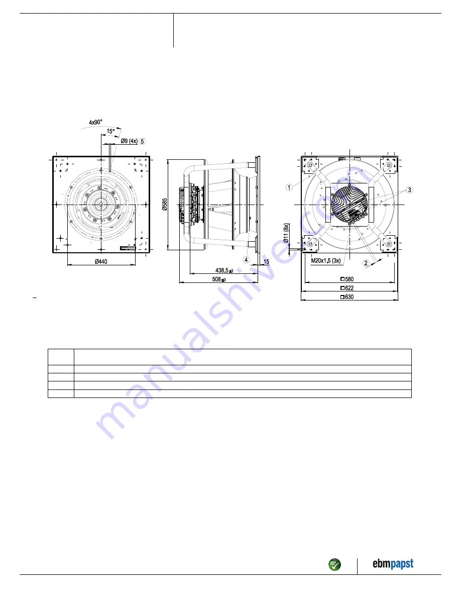
3.1 Product drawing
All measures have the unit mm.
1
Installation position: Shaft horizontal (install the support struts only vertically as shown in the illustration!) or rotor on bottom; rotor on top on
request
2
Cable diameter min. 4 mm, max. 10 mm, tightening torque 4±0.6 Nm
3
Tightening torque 3.5±0.5 Nm
4
Inlet nozzle with pressure tap (k-factor: 281)
5
Mounting holes for FlowGrid
Item no. 54419-5-9970 · ENG · Revision 90170 · Release 2016-07-14 · Page 4 / 12
ebm-papst Mulfingen GmbH & Co. KG · Bachmühle 2 · D-74673 Mulfingen · Phone +49 (0) 7938 81-0 · Fax +49 (0) 7938 81-110 · info1@de.ebmpapst.com · www.ebmpapst.com


