background image

Operating instructions

K3G500-PA23-71

Translation of the original operating instructions

Before working on the electrical connection, the
connections to the mains supply and PE must be shorted.

CAUTION
Electrical voltage

The fan is a built-in component and features no electrically
isolating switch.
→ Only connect the fan to circuits that can be switched off with

an all-pole separating switch.

→ When working on the fan, you must switch off the

installation/machine in which the fan is installed and secure it
from being switched on again.

NOTE
Interferences and failures are possible

Maintain a distance to the power supply line when routing the
control lines of the device.
→ Ensure a sufficiently large clearance.

Recommendation: clearance > 10 cm (separate cable
routing)

NOTE
Water penetration into leads or wires

Water enters at the cable end on the customers side and can
damage the device.
→ Make sure that the cable end is connected in a dry

environment.

Connect the device only to circuits that can be switched off
using an all-pole disconnecting switch.

4.2.1 Prerequisites

;

Check that the data on the type plate match the connection data.

;

Before connecting the device, ensure that the supply voltage matches
the operating voltage of the device.

;

Only use cables designed for current according to the type plate.
For determining the cross-section, follow the basic principles in
accordance with EN 61800-5-1. The protective earth must have a
cross-section equal to or greater than the outer conductor cross-
section.
We recommend the use of 105°C cables. Ensure that the minimum
cable cross-section is at least
AWG26/0.13 mm².

Protective earth contact resistance as per EN 61800-5-1

Compliance with the resistance specifications as per EN 61800-5-1 for
the protective earth connection circuit must be verified in the application.
Depending on the installation situation, it may be necessary to connect
an additional protective earth conductor by way of the extra protective
earth terminal provided on the device. The protective earth terminal is
located on the housing and provided with a protective earth symbol and
a hole.

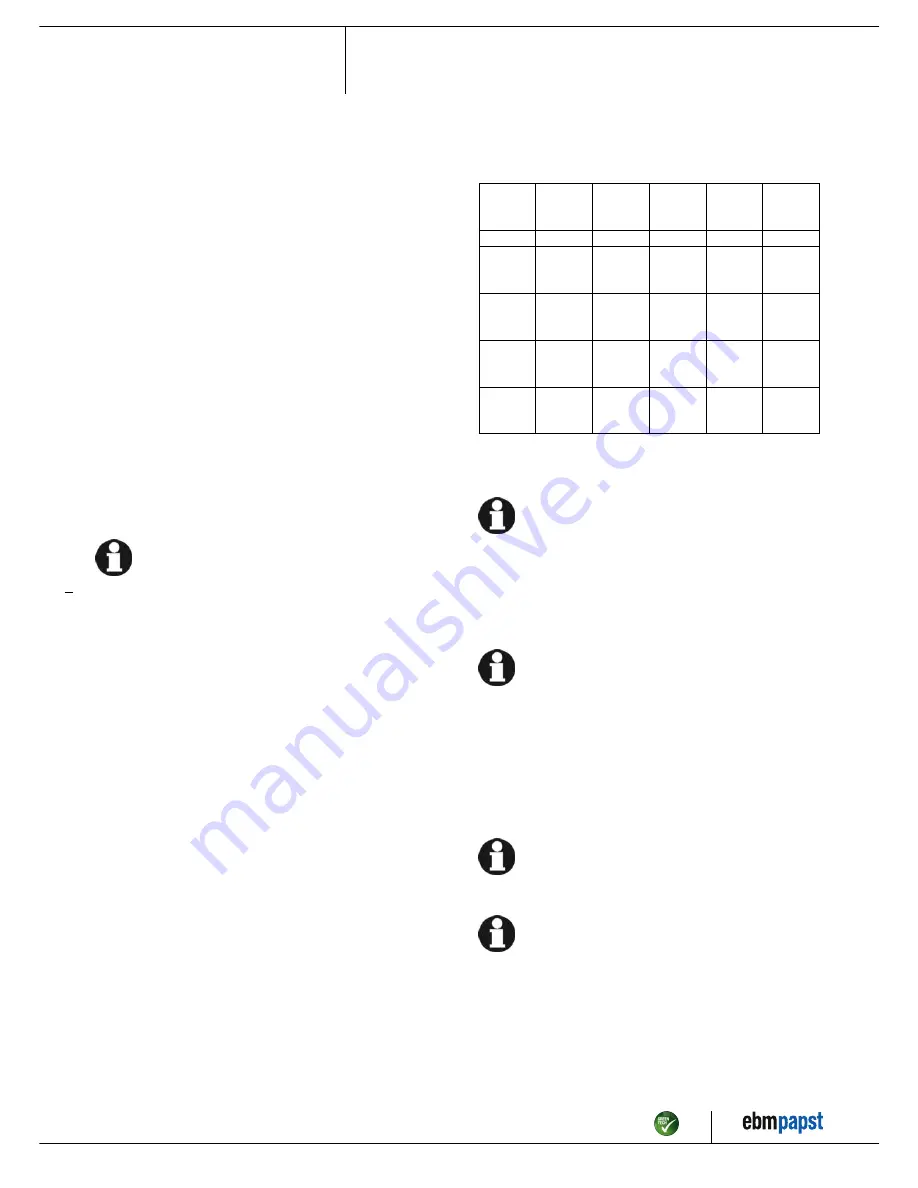
4.2.2 Power supply connection, fuse protection

Assignment of conductor cross-sections and the fuse protection required
for them (overload protection only, no device protection).

Nominal
voltage

Safety
fuse

Automatic
circuit
breaker

Wire
cross-
section

Wire
cross-
section

VDE

UL

VDE

mm²

*AWG

3/PE AC
380 - 480
VAC

16 A

15 A

C16A

1.5

16

3/PE AC
380 - 480
VAC

20 A

20 A

C20A

2.5

14

3/PE AC
380 - 480
VAC

25 A

25 A

C25A

4.0

12

3/PE AC
380 - 480
VAC

32 A

30 A

C32A

6.0

10

* AWG = American Wire Gauge

4.2.3 Idle current

Because of the EMC filter integrated for compliance with EMC
limits (interference emission and interference immunity), idle
currents in the mains cable can be measured even when the
motor is at a standstill and the mains voltage is switched on.

The values are typically in the range < 250 mA

At the same time, the effective power in this operating state
(operational readiness) is typically < 5 W.

4.2.4 Residual current operated device

If the use of a residual current device (RCD) is required in your
installation, only universal residual current devices (type B or
B+) are permissible. Residual current devices (RCD) cannot
provide personal safety while operating the device, as is also
the case with frequency converters. When the device power
supply is switched on, charging current pulses from the
capacitors in the integrated EMC filter can lead to the instant
triggering of residual current devices. We recommend residual
current circuit breakers (RCCB) with an activation threshold of
300 mA and delayed tripping (super-resistant, characteristic K).

4.2.5 Leakage current

For asymmetrical power systems or if a phase fails, the
leakage current can increase to a multiple of the nominal value.

4.2.6 Locked-rotor protection

Due to the locked-rotor protection, the start-up current (LRA) is
equal to or less than the nominal current (FLA).

Item no. 54419-5-9970 · ENG · Revision 90170 · Release 2016-07-14 · Page 7 / 12

ebm-papst Mulfingen GmbH & Co. KG · Bachmühle 2 · D-74673 Mulfingen · Phone +49 (0) 7938 81-0 · Fax +49 (0) 7938 81-110 · info1@de.ebmpapst.com · www.ebmpapst.com

Summary of Contents for K3G500-PA23-71

Page 1: ...arry out a test run and to perform work on the electrical installation 1 3 Basic safety rules 1 1 3 Basic safety rules Any safety hazards stemming from the device must be re evaluated once it is installed in the end device Observe the following when working on the unit Do not make any modifications additions or conversions to the device without the approval of ebm papst 1 4 Electrical voltage 1 1 ...

Page 2: ...ave come to a standstill DANGER Flying parts Missing safety devices may cause balancing weights or broken fan blades to be ejected at high speeds causing bodily harm Take appropriate safety measures WARNING Rotating device Long hair dangling items of clothing jewellery and similar items can become entangled and be pulled into the device Risk of injury Do not wear any loose fitting or dangling clot...

Page 3: ...lowing ways is particularly prohibited and may cause hazards Operating the device with an imbalance e g caused by dirt deposits or icing Resonance mode operation with heavy vibrations These also include vibrations that are transmitted from the customer system to the fan Operation in medical equipment with a life sustaining or lifesaving function Operation with external vibrations Moving solids con...

Page 4: ...own in the illustration or rotor on bottom rotor on top on request 2 Cable diameter min 4 mm max 10 mm tightening torque 4 0 6 Nm 3 Tightening torque 3 5 0 5 Nm 4 Inlet nozzle with pressure tap k factor 281 5 Mounting holes for FlowGrid Item no 54419 5 9970 ENG Revision 90170 Release 2016 07 14 Page 4 12 ebm papst Mulfingen GmbH Co KG Bachmühle 2 D 74673 Mulfingen Phone 49 0 7938 81 0 Fax 49 0 793...

Page 5: ...tion with optimum efficiency The ErP data is determined using a motor impeller combination in a standardised measurement configuration 3 4 Technical features Mass 38 7 kg Size 500 mm Surface of rotor Coated in black Material of electronics housing Die cast aluminium Material of impeller Aluminium sheet Material of mounting plate Sheet steel galvanised Material of support bracket Steel coated in bl...

Page 6: ...at is greater than or equal to 120 times the rated output of the arrangement 4 CONNECTION AND START UP 4 1 Connecting the mechanical system CAUTION Cutting and crushing hazard when removing device from packaging Carefully remove the device from its packaging only touching the housing Strictly avoid shocks Wear safety shoes and cut resistant safety gloves CAUTION Device weighs more than 25 kg Heavy...

Page 7: ...terminal provided on the device The protective earth terminal is located on the housing and provided with a protective earth symbol and a hole 4 2 2 Power supply connection fuse protection Assignment of conductor cross sections and the fuse protection required for them overload protection only no device protection Nominal voltage Safety fuse Automatic circuit breaker Wire cross section Wire cross ...

Page 8: ...ith the seal inserts provided in the terminal box Insert the line s not included in the standard scope of delivery into the terminal box First connect the PE protective earth connection Connect the lines to the corresponding terminals Use a screwdriver to do so During the connection work ensure that no cables splice off Fig 2 Connecting the wires to terminals Seal the terminal box 4 3 3 Cable rout...

Page 9: ...on connection contact rating 250 VAC 2 A AC1 KL 2 5 Din1 Digital input 1 enabling of electronics enabling open pin or applied voltage 5 50 VDC disabling bridge to GND or applied voltage 1 VDC reset function triggers software reset after a level change to 1 V SELV KL 2 6 10 V Fixed voltage output 10 VDC 10 V 3 max 10 mA short circuit proof power supply for external devices e g potentiometer SELV Al...

Page 10: ... off the device Switching off the device during operation Switch off the device via the control input Do not switch the motor e g in cyclic operation on and off via power supply Switching off the device for maintenance work Switch off the device via the control input Do not switch the motor e g in cyclic operation on and off via power supply Disconnect the device from the supply voltage When disco...

Page 11: ...ernatively reset the error message by applying a control signal of 0 5 V to DIN1 or by short circuiting Din1 to GND Unacceptable operating point e g counterpressure is too high Correct the operating point Let the device cool down To reset the error message switch off the mains supply voltage for a min of 25 s and switch it on again Alternatively reset the error message by applying a control signal...

Page 12: ...ogical disposal of the product and its components 6 4 1 Country specific legal requirements NOTE Country specific legal requirements Always observe the applicable country specific legal regulations with regard to the disposal of products or waste occurring in the various phases of the life cycle The corresponding disposal standards are also to be heeded 6 4 2 Disassembly Disassembly of the product...

Reviews: