


Operating instructions
K3G560-AH07-13
Translation of the original operating instructions
4. CONNECTION AND START-UP
4.1 Connecting the mechanical system
CAUTION
Cutting and crushing hazard when removing the fan
from the packaging
→ Carefully remove the fan from its packaging. Make sure to
avoid any shock.
→ Wear safety shoes and cut-resistant safety gloves.
CAUTION
Heavy load when taking out the device
Bodily harm, e.g. back injuries, are possible.
→ Two people should remove the device out of its packaging
together.
;
Check the device for transport damage. Damaged devices must no
longer be installed.
;
Install the undamaged device according to your application.
4.2 Connecting the electrical system
DANGER
Electric voltage on the device
Electric shock
→ Always install a protective earth first.
→ Check the protective earth.
DANGER
Incorrect insulation
Risk of fatal injury from electric shock
→ Use only cables that meet the specified installation
requirements for voltage, current, insulation material, load etc.
→ Route cables such that they cannot be touched by any
rotating parts.
DANGER
Electrical load (>50 µC) between mains wire and
protective earth connection after switching of the supply
when switching multiple devices in parallel.
Electric shock, risk of injury
→ Make sure that sufficient protection against accidental contact
is provided.
Before working on the electrical connection, the
connections to the mains supply and PE must be shorted.
CAUTION
Electrical voltage
The fan is a built-in component and features no electrically
isolating switch.
→ Only connect the fan to circuits that can be switched off with
an all-pole separating switch.
→ When working on the fan, you must switch off the
installation/machine in which the fan is installed and secure it
from being switched on again.
NOTE
Interferences and failures are possible
Maintain a distance to the power supply line when routing the
control lines of the device.
→ Ensure a sufficiently large clearance.
Recommendation: clearance > 10 cm (separate cable
routing)
NOTE
Water penetration into leads or wires
Water enters at the cable end on the customers side and can
damage the device.
→ Make sure that the cable end is connected in a dry
environment.
Connect the device only to circuits that can be switched off
using an all-pole disconnecting switch.
4.2.1 Prerequisites
;
Check whether the data on the type plate agree with the connection
data.
;
Before connecting the device, ensure that the supply voltage matches
the operating voltage of the device.
;
Only use cables designed for current according to the type plate.
For determining the cross-section, follow the basic principles in
accordance with EN 61800-5-1. The protective earth must have a
cross-section equal to or greater than the outer conductor cross-
section.
We recommend the use of 105°C cables. Ensure that the minimum
cable cross-section is at least
AWG26/0.13 mm².
Earth wire contact resistance to EN 61800-5-1
Compliance with the impedance specifications to EN 61800-5-1 for the
protective earth circuit must be verified in the end application.
Depending on the installation situation, it may be necessary to install an
additional protective earthing conductor via the additional protective earth
connection point available on the device.
The protective earth connection point is located on the housing and has
a protective earth symbol and a bore hole.
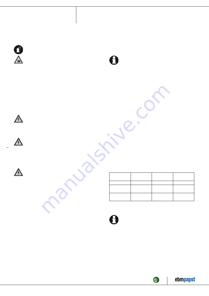
4.2.2 Power supply connection, fuse protection
Assignment of conductor cross-sections and the fuse protection required
for them (overload protection only, no device protection).
Nominal
voltage
Safety fuse
Wire cross-
section
Wire cross-
section
UL
mm²
AWG
3/PE AC 200-
240 VAC
15 A
1.5
16
3/PE AC 200-
240 VAC
20 A
2.5
14
* AWG = American Wire Gauge
4.2.3 Idle current
Because of the EMC filter integrated for compliance with EMC
limits (interference emission and interference immunity), idle
currents in the mains cable can be measured even when the
motor is at a standstill and the mains voltage is switched on.
●
The values lie in a range of typical < 250 mA.
●
The effective power in this operating state (readiness for operation) is
simultaneously at typical < 5 W.
Item no. 50418-5-9970 · Revision 68161 · Release 2010-08-05 · Page 6 / 12
ebm-papst Mulfingen GmbH & Co. KG · Bachmühle 2 · D-74673 Mulfingen · Phone +49 (0) 7938 81-0 · Fax +49 (0) 7938 81-110 · info1@de.ebmpapst.com · www.ebmpapst.com


