background image

Operating instructions

K3G560-AH07-13

Translation of the original operating instructions

4.2.4 Residual current operated device

Only universal (type B or B+) RCD protective devices are
permitted. Like frequency inverters, RCD protective devices
cannot provide personal safety while operating the device.
When switching on the power supply of the device, pulsed
charge currents from the capacitors in the integrated EMC filter
can lead to the RCD protective devices triggering without
delay. We recommend residual current devices with a trigger
threshold of 300 mA and delayed triggering (super-resistant,
characteristic K).

4.2.5 Leakage current

For asymmetrical power systems or if a phase fails, the
leakage current can increase to a multiple of the nominal value.

4.2.6 Locked-rotor protection

Due to the locked-rotor protection, the start-up current (LRA) is
equal to or less than the nominal current (FLA).

4.3 Connection in terminal box

4.3.1 Preparing connection lines for the connection

Strip the cable just enough so that the screwed cable gland is tight and
the terminals are relieved of strain. Tightening torque, see chapter 3.1
Product drawing.

Ill. 1: Recommended stripping lengths in mm (inside the terminal box)

4.3.2 Connecting cables with terminals

WARNING
Terminals and connections have voltage even with a
unit that is shut off

Electric shock
→ Wait five minutes after disconnecting the voltage at all poles

before opening the device.

;

Remove the cap from the screwed cable gland.

Remove the cap only in those places where cables are inserted.

;

Mount the screwed cable glands with the seal inserts provided in the
terminal box.

;

Insert the line(s) (not included in the standard scope of delivery) into
the terminal box.

;

First connect the "PE" (protective earth) connection.

;

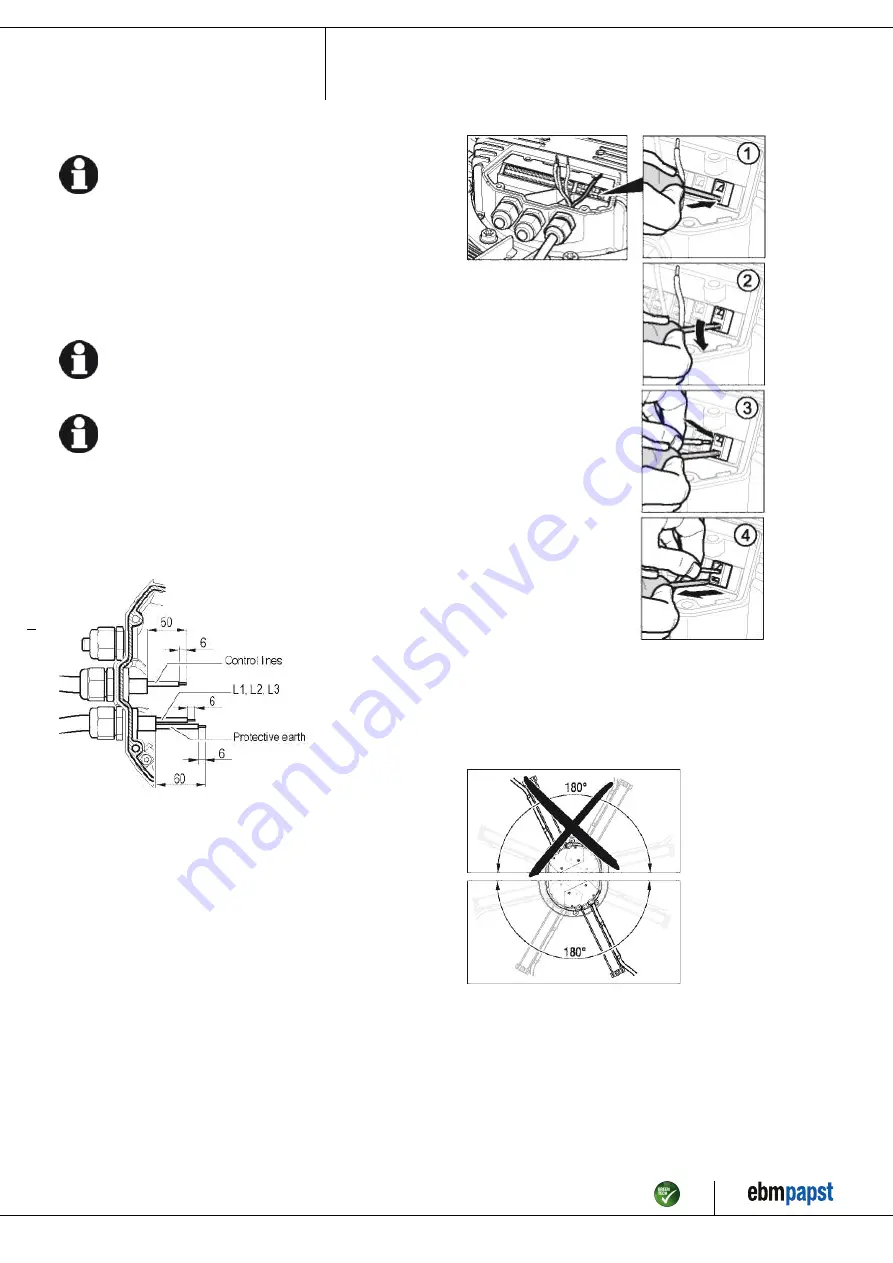
Connect the lines to the corresponding terminals.

Use a screwdriver to do so.
During the connection work, ensure that no cables splice off.

Ill. 2: Connecting the wires to terminals

;

Seal the terminal box.

4.3.3 Cable routing

No water may penetrate along the cable in the direction of the cable gland.
When routing the cable, ensure that the screwed cable glands are
arranged at the bottom. The cables must always be routed downwards.

Ill. 3: Cable routing for fans installed upright.

Item no. 50418-5-9970 · Revision 68161 · Release 2010-08-05 · Page 7 / 12

ebm-papst Mulfingen GmbH & Co. KG · Bachmühle 2 · D-74673 Mulfingen · Phone +49 (0) 7938 81-0 · Fax +49 (0) 7938 81-110 · info1@de.ebmpapst.com · www.ebmpapst.com

Summary of Contents for K3G560-AH07-13

Page 1: ...transport unpack assemble operate or maintain the device or to use it in any other manner 1 3 Basic safety rules 1 1 3 Basic safety rules Any safety hazards stemming from the device must be re evalua...

Page 2: ...g on the system machine wait until all parts have come to a standstill DANGER Flying parts Missing safety devices may cause balancing weights or broken fan blades to be ejected at high speeds causing...

Page 3: ...imbalance e g caused by dirt deposits or icing Operation in medical equipment with a life sustaining or lifesaving function Operation with external vibrations Moving solids content in flow medium Pai...

Page 4: ...l measures have the unit mm 1 Cable diameter min 4 mm max 10 mm tightening torque 4 0 6 Nm 2 Tightening torque 3 5 0 5 Nm Item no 50418 5 9970 Revision 68161 Release 2010 08 05 Page 4 12 ebm papst Mul...

Page 5: ...on Reverse polarity and locked rotor protection Protection class I if protective earth is connected by customer Product conforming to standard EN 61800 5 1 CE Approval GOST UL 2111 CSA C22 2 Nr 77 For...

Page 6: ...nters at the cable end on the customers side and can damage the device Make sure that the cable end is connected in a dry environment Connect the device only to circuits that can be switched off using...

Page 7: ...r 3 1 Product drawing Ill 1 Recommended stripping lengths in mm inside the terminal box 4 3 2 Connecting cables with terminals WARNING Terminals and connections have voltage even with a unit that is s...

Page 8: ...tion mode PWM controlling Group adress 1 Fan device adress 1 Max PWM 100 Min PWM 0 Save set value to EEPROM Yes Set value control Analog Control function Positive heating Item no 50418 5 9970 Revision...

Page 9: ...te to 100 level control coefficient KL3 2 8 GND Reference mass for control interface SELV KL3 3 7 0 10 V Use control actual value input 0 10 VDC impedance 100 k only as alternative to 4 20 mA input SE...

Page 10: ...ng off the device during operation Switch on the device via the control input Do not switch the motor e g in cyclic operation on and off via power supply Switching off the device for maintenance work...

Page 11: ...ght clips during cleaning make sure to remove them afterwards Motor does not turn Mechanical blockage Switch off de energise and remove mechanical blockage Mains supply voltage faulty Check mains supp...

Page 12: ...y 6 months Repair or replacement of the device Check the device for damage to blades and housing Visual inspection At least every 6 months Replacement of the device Mounting the connection lines Visua...

Reviews: