background image

Operating instructions

K3G710-PV05-02

Translation of the original operating instructions

4.2.2 Supply connection and fuses

Assignment of supply cable cross-sections and their required fuses (line
protection only, no equipment protection).

Nominal
voltage

Fuse

Automatic
circuit
breaker

Cable
cross-
section

Cable
cross-
section

VDE

UL

VDE

mm²

*AWG

3/PE AC
380-480
VAC

20 A

20 A

C20A

2.5

14

3/PE AC
380-480
VAC

25 A

25 A

C25A

4.0

12

* AWG = American Wire Gauge

4.2.3 Reactive currents

Because of the EMC filter integrated for compliance with EMC
limits (interference emission and immunity to interference),
reactive currents can be measured in the supply line even
when the motor is at a standstill and the line voltage is switched
on.

The values are typically in the range < 500 mA.

At the same time, the effective power in this operating state
(operational readiness) is typically < 6 W.

4.2.4 Residual current circuit breaker (RCCB)

If the use of a residual current device (RCD) is required in your
installation, only AC/DC-sensitive residual current devices
(type B or B+) are permissible. As with variable frequency
drives, residual current devices cannot provide personal safety
while operating the device. When the device power supply is
switched on, pulsed charging currents from the capacitors in the
integrated EMC filter can lead to the instant tripping of residual
current devices. We recommend the use of residual current
circuit breakers (RCCB) with a trip threshold of 300 mA and
delayed tripping (super-resistant, characteristic K).

4.2.5 Leakage current

For asymmetrical power systems or if a phase fails, the
leakage current can increase to a multiple of the nominal value.

4.2.6 Locked-rotor protection

Due to the locked-rotor protection, the starting current (LRA) is
equal to or less than the nominal current (FLA).

4.3 Connection in terminal box

4.3.1 Preparing cables for connection

Only strip the cable as far as necessary, ensuring that the cable gland is
sealed and there is no strain on the connections. For tightening torques,
see Chapter 3.1 Product drawing.

NOTE
Tightness and strain relief are dependent on the cable
used.

→ This must be checked by the user.

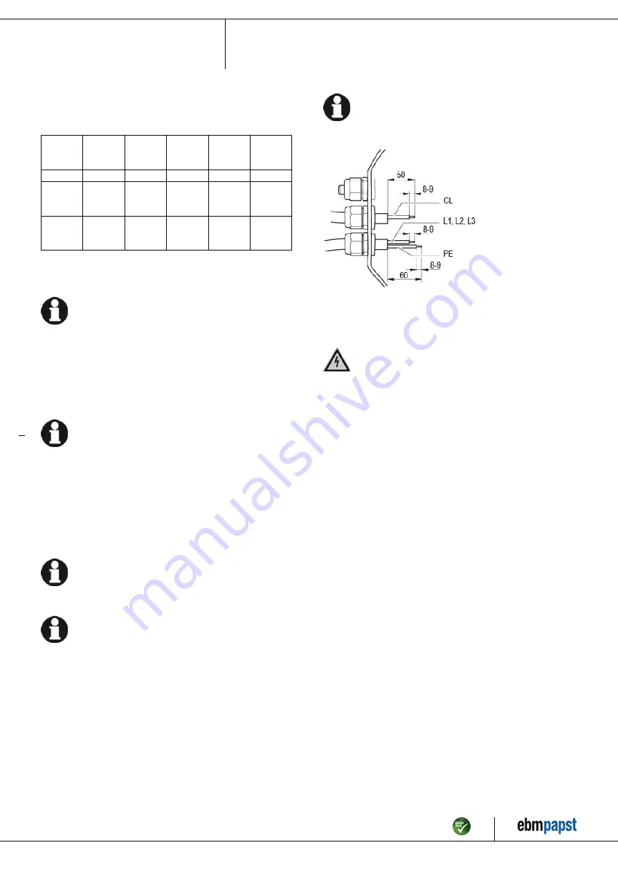
Fig. 3: Recommended stripped lengths in mm (inside terminal box)
Legend: CL = control lines

4.3.2 Connecting wires to terminals

WARNING
Live terminals and connections even with device
switched off

Electric shock
→ Wait five minutes after disconnecting the voltage at all poles

before opening the device.

;

Remove the cap from the cable gland.

Only remove caps where cables are fed in.

;

Route the wire(s) (not included in scope of delivery) into the terminal
box.

;

First connect the "PE" (protective earth).

;

Connect the wires to the corresponding terminals.

Use a screwdriver to do so.
When connecting, ensure that no wire ends fan out.

Item no. 55980-5-9970 · ENU · Change 212420 · Approved 2020-02-17 · Page 8 / 15

ebm-papst Mulfingen GmbH & Co. KG · Bachmühle 2 · D-74673 Mulfingen · Phone +49 (0) 7938 81-0 · Fax +49 (0) 7938 81-110 · info1@de.ebmpapst.com · www.ebmpapst.com

Summary of Contents for K3G710-PV05-02

Page 1: ...permitted to install the device to carry out a test run and to perform work on the electrical installation 1 3 Basic safety rules 1 1 3 Basic safety rules The safety hazards associated with the devic...

Page 2: ...GER Ejected parts Missing protective devices may cause balancing weights or broken fan blades to be ejected and cause injuries Take appropriate safety measures WARNING Rotating device Long hair and da...

Page 3: ...forming all maintenance work Conveying air at an ambient air pressure between 800 mbar and 1050 mbar Using the device within the permitted ambient temperature range see Chapter 3 6 Transport and stora...

Page 4: ...ghtening torque 6 0 9 Nm 5 Tightening torque 3 5 0 5 Nm 6 Attachment holes for FlowGrid 50710 2 2957 not included in scope of delivery 7 Motor support plate Installation position shaft horizontal moto...

Page 5: ...ription Weight 120 7 kg Size 710 mm Motor size 200 Rotor surface Painted black Electronics housing material Die cast aluminum painted black Impeller material Sheet aluminum painted black Support plate...

Page 6: ...t of the arrangement It is the responsibility of the installation engineer or operator owner of the device to ensure if necessary after consultation with the network operator that this device is only...

Page 7: ...re working on the electrical hookup short the supply and PE connections CAUTION Voltage The fan is a built in component and has no disconnecting switch Only connect the fan to circuits that can be swi...

Page 8: ...se of residual current circuit breakers RCCB with a trip threshold of 300 mA and delayed tripping super resistant characteristic K 4 2 5 Leakage current For asymmetrical power systems or if a phase fa...

Page 9: ...possible If this is not possible a drip edge can be produced by fitting a cable tie directly in front of the cable gland for example 4 4 Factory settings Factory settings made for the device by ebm p...

Page 10: ...tact changeover contact common connection contact rating 250 VAC max 2 A AC1 min 10 mA KL2 3 NC Status relay floating status contact break for failure KL 3 1 RSA Bus connection RS485 RSA MODBUS RTU SE...

Page 11: ...PROM setting the integrated controller s direction of action can be selected via bus or digital input Din3 normal pin open or applied voltage 5 50 VDC inverse bridge to GND or applied voltage 1 VDC SE...

Page 12: ...ng Either run through the resonant range as quickly as possible with speed control or find another remedy Operation with excessively high vibration levels can lead to premature failure The maximum per...

Page 13: ...e from supply and remove mechanical blockage Line voltage faulty Check line voltage restore power supply Attention The error message resets automatically Device restarts automatically without warning...

Page 14: ...aintenance intervals to the actual level of dust exposure 6 3 Safety inspection NOTE High voltage test The integrated EMC filter has Y capacitors The tripping current is exceeded when AC testing volta...

Page 15: ...tallic materials are generally considered to be fully recyclable Separate the components for recycling into the following categories Steel and iron Aluminum Non ferrous metal e g motor windings Plasti...

Reviews: