


Operating instructions
M1G055-BI19-12
Translation of the original operating instructions
4. CONNECTION AND STARTUP
4.1 Mechanical connection
WARNING
Hot motor housing
Risk of fire
→ Ensure that no combustible or flammable materials are
located close to the motor.
CAUTION
Cutting and crushing hazard when removing motor from
packaging
→ Carefully remove the device from its packaging. Strictly
avoid shocks.
→ Wear safety shoes and cut-resistant safety gloves.
;
Check the device for transport damage. Damaged devices are not to
be installed.
;
Install the undamaged device in accordance with your application.
CAUTION
Possible damage to the device
If the device slips during installation, serious damage can result.
→ Ensure that the device is securely positioned at its place of
installation until all fastening screws have been tightened.
4.2 Electrical connection
DANGER
Faulty insulation
Risk of fatal injury from electric shock
→ Use only cables that meet the specified installation
regulations for voltage, current, insulation material, capacity,
etc.
→ Route cables so that they cannot be touched by any
rotating parts.
CAUTION
Voltage
The motor is a built-in component and has no disconnecting
switch.
→ Only connect the motor to circuits that can be switched off
with an all-pole disconnection switch.
→ When working on the motor, secure the system/machine
in which the motor is installed so as to prevent it from being
switched back on.
NOTE
Water ingress into wires or cables
Water ingress at the customer end of the cable can damage the
device.
→ Make sure the end of the cable is connected in a dry
environment.
Only connect the device to circuits that can be switched off with
an all-pole disconnection switch.
4.2.1 Requirements
;
Check whether the information on the nameplate matches the
connection data.
;
Before connecting the device, make sure the power supply matches
the device voltage.
;
Only use cables designed for the current level indicated on the
nameplate.
For determining the cross-section, note the sizing criteria according
to EN 61800-5-1. The protective earth must have a cross-section
equal to or greater than that of the phase conductor.
We recommend the use of 105 °C cables. Ensure that the minimum
cable cross-section is at least
AWG 26 / 0.13 mm².
4.2.2 Reactive currents
Because of the EMC filter integrated for compliance with EMC
limits (interference emission and immunity to interference),
reactive currents can be measured in the supply line even
when the motor is at a standstill and the line voltage is switched
on.
●
The values are typically in the range < 50 mA
●
At the same time, the effective power in this operating state
(operational readiness) is typically < 2 W.
4.2.3 Locked-rotor protection
Due to the locked-rotor protection, the starting current (LRA) is
equal to or less than the nominal current (FLA).
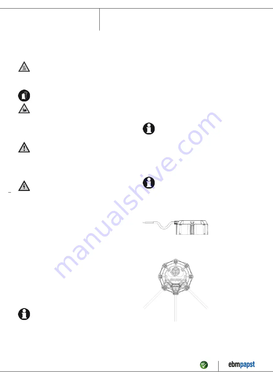
4.3 Routing of cables
It must not be possible for water to run along the cable towards the cable
exit.
Installation with motor shaft vertical
Fig. 1: Installation with motor shaft vertical, cable routed in U-shaped loop
;
Make sure the cable is routed in a U-shaped loop.
Installation with motor shaft horizontal
Fig. 2: Cable routing for installation with motor shaft horizontal. The
cables must always be routed downward.
Item no. 55927-5-9970 · ENU · Change 94089 · Approved 2017-08-15 · Page 6 / 11
ebm-papst Mulfingen GmbH & Co. KG · Bachmühle 2 · D-74673 Mulfingen · Phone +49 (0) 7938 81-0 · Fax +49 (0) 7938 81-110 · info1@de.ebmpapst.com · www.ebmpapst.com


