
Operating instructions
P2E076-AC06-01
Translation of the original operating instructions
4. CONNECTION AND START-UP
4.1 Connecting the mechanical system
WARNING
Hot motor housing
Fire hazard
→ Ensure that no combustible or flammable materials are
located close to the pump.
CAUTION
Cutting and crushing hazard when removing the pump
from the packaging
→ Carefully remove the device from its packaging. Make sure
to avoid any shock.
→ Wear safety shoes and cut-resistant safety gloves.
;
Check the device for transport damage. Damaged devices must no
longer be installed.
;
Install the undamaged device according to your application.
4.2 Connecting the electrical system
DANGER
Electric voltage on the device
Electric shock
→ Always install a protective earth first.
→ Check the protective earth.
DANGER
Incorrect insulation
Risk of fatal injury from electric shock
→ Use only cables that meet the specified installation
requirements for voltage, current, insulation material, load etc.
→ Route cables such that they cannot be touched by any
rotating parts.
CAUTION
Electrical voltage
The pump is a built-in component and features no electrically
isolating switch.
→ Only connect the pump to circuits that can be switched off
with an all-pole separating switch.
→ When working on the pump, you must switch off the
system/machine in which the pump is installed and secure it
from being switched on again.
NOTE
Water penetration into leads or wires
Water enters at the cable end on the customers side and can
damage the device.
→ Make sure that the cable end is connected in a dry
environment.
Connect the device only to circuits that can be switched off
using an all-pole disconnecting switch.
4.2.1 Prerequisites
;
Check whether the data on the type plate agree with the connection
data and the data of the operating capacitor.
;
Before connecting the device, ensure that the supply voltage matches
the operating voltage of the device.
;
Only use cables designed for current according to the type plate.
For determining the cross-section, follow the basic principles in
accordance with EN 61800-5-1. The protective earth must have a
cross-section equal to or greater than the outer conductor cross-
section.
We recommend the use of 105°C cables. Ensure that the minimum
cable cross-section is at least
AWG26/0.13 mm².
4.2.2 Voltage control
With open loop speed control using transformers or electronic
voltage regulators (e.g. phase angle control), excessive current
may occur.
In addition, noises can occur with phase angle control
depending on the mounting situation.
4.2.3 Frequency inverter
Fit sinusoidal filters that work on all poles (live-live and live-
earth) between the frequency inverter and the motor for
operation with frequency inverters.
Depending on how the device is installed, noises may occur.
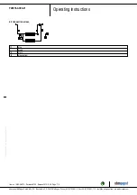
4.3 Connection of the cables
External leads are brought out of device.
;
First connect the "PE" (protective earth) connection.
;
Connect the lines according to your application. When doing so,
observe chapter 4.4 Connection screen.
Item no. 10615-5-9970 · Revision 68158 · Release 2010-11-29 · Page 6 / 9
ebm-papst Mulfingen GmbH & Co. KG · Bachmühle 2 · D-74673 Mulfingen · Phone +49 (0) 7938 81-0 · Fax +49 (0) 7938 81-110 · info1@de.ebmpapst.com · www.ebmpapst.com


