background image

Operating instructions

R3G220-RY90-P1

Translation of the original operating instructions

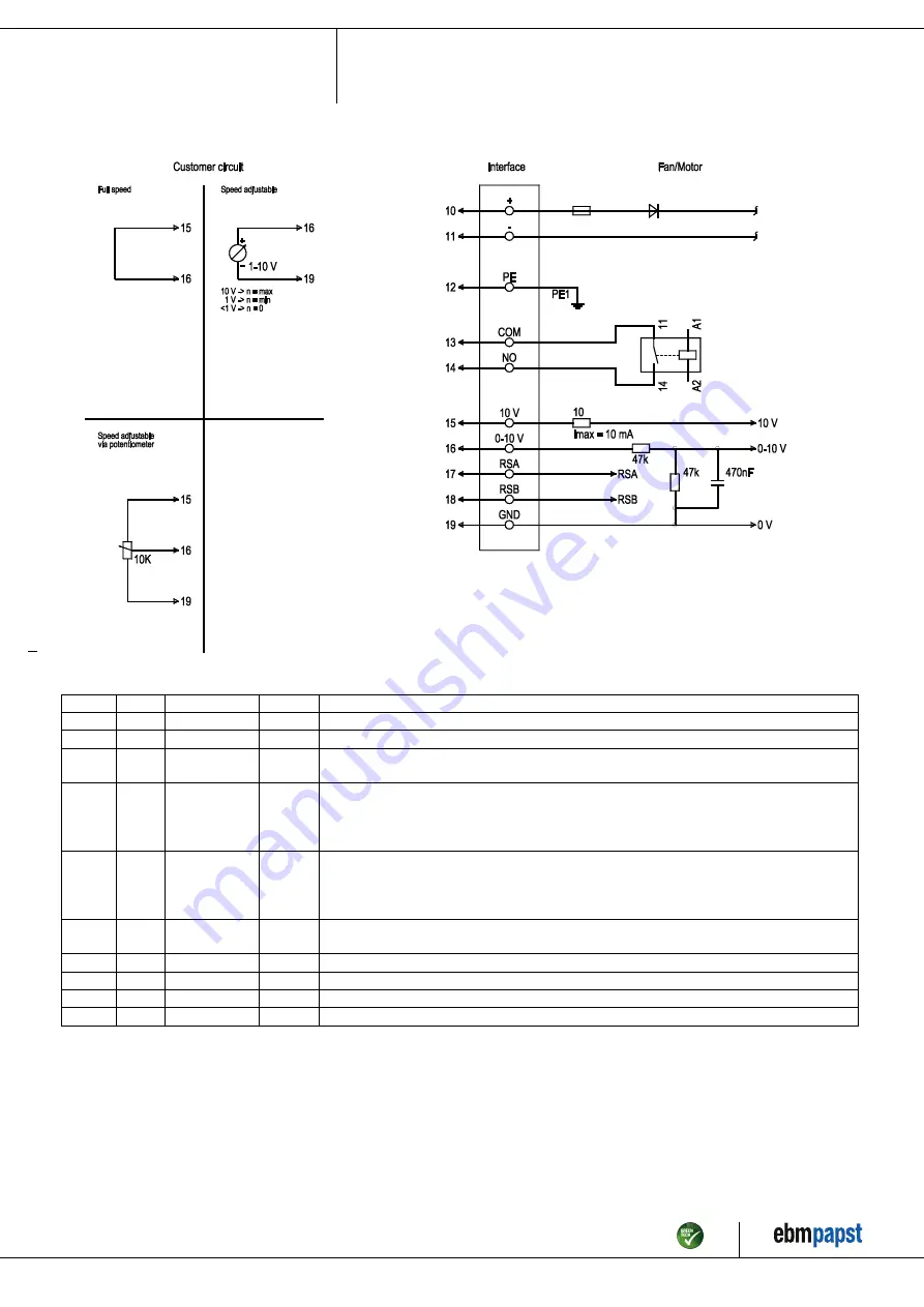
4.4 Connection diagram

Drawing preliminary!

No.

Conn.

Designation

Color

Function/assignment

10

+

brown

Power supply, see nameplate for voltage range

11

-

black

Power supply, see nameplate for voltage range

12

PE

green/
yellow

Protective earth

13

COM

gray

Status relay, floating status contact, common connection, contact rating
250 VAC/30 VDC max. 2 A (AC1), min. 1 mA/5 VDC,
reinforced insulation on control interface side, basic insulation on supply side in accordance with
EN 50124-1

14

NO

purple

Status relay, floating status contact, normally open contact, contact rating
250 VAC/30 VDC max. 2 A (AC1), min. 1 mA/5 VDC,
reinforced insulation on control interface side, basic insulation on supply side in accordance with
EN 50124-1

15

+10 V

red

Fixed voltage output 10 VDC, SELV, +10 V +/-3%, max. 10 mA, short-circuit-proof, power
supply for external devices (e.g. potentiometers)

16

0-10 V

yellow

Analog input (set value) SELV, 0-10 V, Ri = 100 kΩ, adjustable curve

17

RSA

white

RS-485 interface for MODBUS, RSA; SELV, bus termination resistor provided by customer

18

RSB

orange

RS-485 interface for MODBUS, RSB; SELV, bus termination resistor provided by customer

19

GND

blue

Reference ground for control interface, SELV

Item no. 57069-5-9970 · ENU · Change 262073 · Approved 2022-10-04 · Page 8 / 11

ebm-papst Mulfingen GmbH & Co. KG · Bachmühle 2 · D-74673 Mulfingen · Phone +49 (0) 7938 81-0 · Fax +49 (0) 7938 81-110 · info1@de.ebmpapst.com · www.ebmpapst.com

Summary of Contents for R3G220-RY90-P1

Page 1: ...ed maintained and otherwise used by suitably qualified trained and authorized technical staff Only authorized specialists are permitted to install the device to carry out a test run and to perform wor...

Page 2: ...ding measures have to be taken by the user NOTE Electrical or electromagnetic interference after installing the device in customer equipment Verify that the entire setup is EMC compliant 1 7 Mechanica...

Page 3: ...he device in the following ways is prohibited and could be hazardous Operating the device in an unbalanced state e g due to dirt deposits or ice formation Resonant operation operation with severe vibr...

Page 4: ...ole prepared for self tapping M4 screw max clearance for screw 8 mm 3 Tapping hole prepared for self tapping M4 screw max clearance for screw 10 mm 4 Cable halogen free railway application EN 45545 10...

Page 5: ...All dimensions in mm Inlet ring 09609 2 4013 not included in scope of delivery Item no 57069 5 9970 ENU Change 262073 Approved 2022 10 04 Page 5 11 ebm papst Mulfingen GmbH Co KG Bachm hle 2 D 74673 M...

Page 6: ...tion and connection Conformity with standards EN 45545 2 HL3 EN 50155 EN 61373 Cat 1B Approval EAC Comment A prerequisite for operation is a Class 1 vehicle electrical system architecture according to...

Page 7: ...earth connection after switching off supply with multiple devices connected in parallel Electric shock risk of injury Ensure sufficient protection against accidental contact Before working on the ele...

Page 8: ...t rating 250 VAC 30 VDC max 2 A AC1 min 1 mA 5 VDC reinforced insulation on control interface side basic insulation on supply side in accordance with EN 50124 1 15 10 V red Fixed voltage output 10 VDC...

Page 9: ...ation on and off via power supply Disconnect the device from the power supply When disconnecting be sure to disconnect the ground connection last 5 MAINTENANCE MALFUNCTIONS POSSIBLE CAUSES AND REMEDIE...

Page 10: ...esource preservation are top priority corporate goals ebm papst operates an environmental management system which is certified in accordance with ISO 14001 and rigorously implemented around the world...

Page 11: ...ploying the proper procedures for electronic scrap Please contact ebm papst for any other questions on disposal Item no 57069 5 9970 ENU Change 262073 Approved 2022 10 04 Page 11 11 ebm papst Mulfinge...

Reviews: