background image

Operating instructions

R3G250-AY11-C1

Translation of the original operating instructions

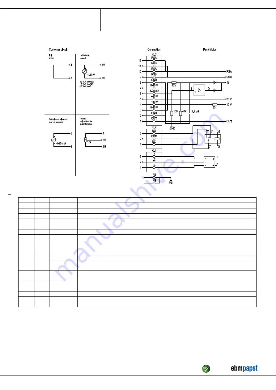
4.5 Connection diagram

Drawing preliminary!

No.

Conn.

Designation

Function/assignment

PE

PE

Protective earth terminal

KL1

1, 2, 3

L1, L2, L3

Power supply, voltage range (see nameplate), 50/60 Hz

KL2

1

NC

Floating status contact, break for failure

KL2

2

COM

floating status contact, changeover contact, common connection (2 A, max. 250 VAC,
min. 10 mA, AC1)

KL2

3

NO

Floating status contact, make for failure

KL3

1

OUT

Analog output, 0-10 VDC, max. 3 mA, SELV,
output of current motor modulation level:
1 V corresponds to 10% modulation level.
10 V corresponds to 100% modulation level.

KL3

2, 8

GND

Reference ground for control interface, SELV

KL3

3, 7

0-10 V

Use control / current sensor value input 0-10 VDC, impedance 100 kΩ only as alternative to 4-20 mA input,
SELV

KL3

4

+10 V

Voltage output 10 VDC (±3%), max. 10 mA, power supply for external devices
(e.g. potentiometer), SELV

KL3

5

+20 V

Voltage output 20 VDC (+25%/-10%), max. 50 mA, power supply for external devices
(e.g. sensors), SELV

KL3

6

4-20 mA

Use control / current sensor value input 4-20 mA, impedance 100 Ω only as alternative to 0-10 V input, SELV

KL3

9, 11

RSB

RS485 interface for MODBUS, RSB

KL3

10, 12

RSA

RS485 interface for MODBUS, RSA

Item no. 51240-5-9970 · ENU · Change 211950 · Approved 2020-09-21 · Page 9 / 13

ebm-papst Mulfingen GmbH & Co. KG · Bachmühle 2 · D-74673 Mulfingen · Phone +49 (0) 7938 81-0 · Fax +49 (0) 7938 81-110 · info1@de.ebmpapst.com · www.ebmpapst.com

Summary of Contents for R3G250-AY11-C1

Page 1: ...lists are permitted to install the device to carry out a test run and to perform work on the electrical installation 1 3 Basic safety rules 1 1 3 Basic safety rules The safety hazards associated with...

Page 2: ...er equipment Verify that the entire setup is EMC compliant 1 7 Mechanical movement DANGER Rotating device Risk of injury to body parts coming into contact with the rotor or the impeller Secure the dev...

Page 3: ...use In particular operating the device in the following ways is prohibited and could be hazardous Operating the device in an unbalanced state e g due to dirt deposits or ice formation Resonant operat...

Page 4: ...essure tap k factor 70 not included in scope of delivery 2 Max clearance for screw 16 mm 3 Cable diameter min 4 mm max 10 mm tightening torque 2 5 0 4 Nm 4 Tightening torque 3 5 0 5 Nm Item no 51240 5...

Page 5: ...ned at optimum efficiency level The ErP data is determined using a motor impeller combination in a standardized measurement setup 3 4 Technical description Weight 6 4 kg Size 250 mm Motor size 84 Roto...

Page 6: ...tor that this device is only connected to a connection point with a Ssc value that is greater than or equal to 120 times the rated output of the arrangement 4 CONNECTION AND STARTUP 4 1 Mechanical con...

Page 7: ...ominal voltage Fuse Automatic circuit breaker Cable cross section Cable cross section VDE UL VDE mm AWG 3 PE AC 380 480 VAC 16 A 15 A C16A 1 5 2 5 16 AWG American Wire Gauge 4 2 3 Reactive currents Be...

Page 8: ...box if water is constantly present at the cable glands To prevent the constant accumulation of water at the cable glands the cable should be routed in a U shaped loop wherever possible If this is not...

Page 9: ...to 100 modulation level KL3 2 8 GND Reference ground for control interface SELV KL3 3 7 0 10 V Use control current sensor value input 0 10 VDC impedance 100 k only as alternative to 4 20 mA input SELV...

Page 10: ...supply Switching off the device for maintenance Switch off the device via the control input Do not switch the motor e g in cyclic operation on and off via power supply Disconnect the device from the...

Page 11: ...ect the operating point Let the device cool down To reset the error message switch off the line voltage for at least 25 s and then switch it on again Alternatively reset the error message by applying...

Page 12: ...mal bearing noise acoustic At least every 6 months Replace device 6 4 Disposal For ebm papst environmental protection and resource preservation are top priority corporate goals ebm papst operates an e...

Page 13: ...pose of electronic components employing the proper procedures for electronic scrap Please contact ebm papst for any other questions on disposal Item no 51240 5 9970 ENU Change 211950 Approved 2020 09...

Reviews: