background image

Operating instructions

R3G250-PR17-I1

Translation of the original operating instructions

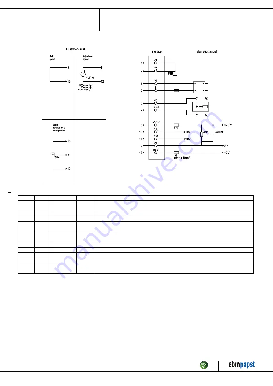
4.5 Connection diagram

Drawing preliminary!

No.

Conn.

Designation

Color

Function/assignment

1

1, 2

PE

green/
yellow

Protective earth

1

3

N

blue

Power supply, neutral conductor, 50/60 Hz

1

5

L

black

Power supply, phase, 50/60 Hz

1

6

NC

white 1

Status relay, floating status contact; break for failure, contact rating 250 VAC / 2A (AC1) / min. 10
mA, basic insulation on supply side and reinforced insulation on control interface side

1

7

COM

white 2

Status relay, floating status contact; common connection, contact rating 250 VAC / 2A (AC1) / min.
10 mA, basic insulation on supply side and reinforced insulation on control interface side

2

8

0-10V

yellow

Analog input (set value); 0-10 V; Ri = 100 kΩ; adjustable curve

2

10

RSB

brown

RS485 interface for MODBUS, RSB

2

11

RSA

white

RS485 interface for MODBUS, RSA

2

12

GND

blue

Reference ground for control interface, SELV

2

13

+10V

red

Fixed voltage output 10 VDC, +10 V ±3%; max. 10 mA; short-circuit-proof; power supply for
external devices (e.g. pot)

Item no. 54443-5-9970 · ENU · Change 229573 · Approved 2021-06-09 · Page 9 / 12

ebm-papst Mulfingen GmbH & Co. KG · Bachmühle 2 · D-74673 Mulfingen · Phone +49 (0) 7938 81-0 · Fax +49 (0) 7938 81-110 · info1@de.ebmpapst.com · www.ebmpapst.com

Summary of Contents for R3G250-PR17-I1

Page 1: ...are permitted to install the device to carry out a test run and to perform work on the electrical installation 1 3 Basic safety rules 1 1 3 Basic safety rules The safety hazards associated with the de...

Page 2: ...y that the entire setup is EMC compliant 1 7 Mechanical movement DANGER Rotating device Risk of injury to body parts coming into contact with the rotor or the impeller Secure the device against accide...

Page 3: ...ctions Improper use In particular operating the device in the following ways is prohibited and could be hazardous Operating the device in an unbalanced state e g due to dirt deposits or ice formation...

Page 4: ...13 with pressure tap k factor 76 not included in scope of delivery 2 Max clearance for screw 16 mm 3 Cable PVC AWG18 5x crimped ferrules 4 Cable PVC AWG22 5x crimped ferrules Item no 54443 5 9970 ENU...

Page 5: ...s All dimensions in mm Inlet ring 96355 2 4013 with pressure tap k factor 76 Item no 54443 5 9970 ENU Change 229573 Approved 2021 06 09 Page 5 12 ebm papst Mulfingen GmbH Co KG Bachm hle 2 D 74673 Mul...

Page 6: ...ation in a standardized measurement setup 3 4 Technical description Weight 4 683 kg Size 250 mm Motor size 84 Rotor surface Painted black Impeller material PP plastic Housing material Die cast aluminu...

Page 7: ...Mechanical connection CAUTION Cutting and crushing hazard when removing fan from packaging Carefully remove the device from its packaging by the fan impeller Strictly avoid shocks Wear safety shoes a...

Page 8: ...ctive currents can be measured in the supply line even when the motor is at a standstill and the line voltage is switched on The values are typically in the range 250 mA At the same time the effective...

Page 9: ...relay floating status contact common connection contact rating 250 VAC 2A AC1 min 10 mA basic insulation on supply side and reinforced insulation on control interface side 2 8 0 10V yellow Analog inpu...

Page 10: ...ound connection last 5 INTEGRATED PROTECTIVE FEATURES The integrated protective functions cause the motor to switch off automatically in the event of the faults described in the table Fault Safety fea...

Page 11: ...vibration that will shorten the service life of the fan Severe vibration can destroy the fan In such cases switch off the fan immediately and clean it The preferred method of cleaning is dry cleaning...

Page 12: ...y of the product must be performed or supervised by qualified personnel with the appropriate technical knowledge The product is to be disassembled into suitable components for disposal employing stand...

Reviews: