background image

Operating instructions

R3G250-RR09-P1

Translation of the original operating instructions

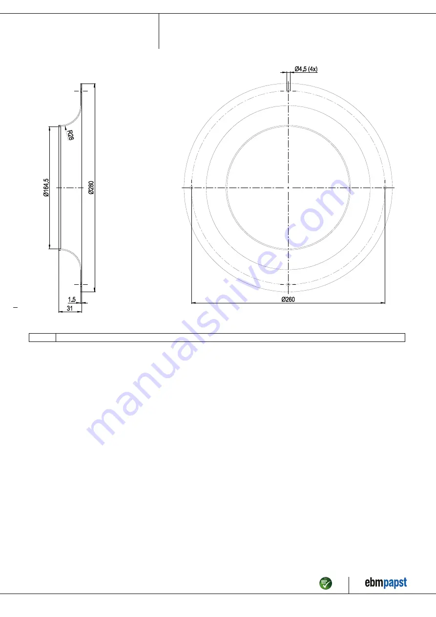
All dimensions in mm.

Inlet ring 96420-2-4013

Item no. 53889-5-9970 · ENU · Change 235485 · Approved 2021-12-14 · Page 5 / 12

ebm-papst Mulfingen GmbH & Co. KG · Bachmühle 2 · D-74673 Mulfingen · Phone +49 (0) 7938 81-0 · Fax +49 (0) 7938 81-110 · info1@de.ebmpapst.com · www.ebmpapst.com

Summary of Contents for R3G250-RR09-P1

Page 1: ...ff Only authorized specialists are permitted to install the device to carry out a test run and to perform work on the electrical installation 1 3 Basic safety rules 1 1 3 Basic safety rules The safety...

Page 2: ...mpliant 1 7 Mechanical movement DANGER Rotating device Risk of injury to body parts coming into contact with the rotor or the impeller Secure the device against accidental contact Before working on th...

Page 3: ...he device in the following ways is prohibited and could be hazardous Operating the device in an unbalanced state e g due to dirt deposits or ice formation Resonant operation operation with severe vibr...

Page 4: ...clearance for screw 16 mm 3 Cable halogen free railway application EN 45545 4G 1 5 mm 3x wire end ferrule 1x wire not routed externally 4 Cable halogen free railway application EN 45545 7x 0 5 mm 7x...

Page 5: ...ing instructions All dimensions in mm Inlet ring 96420 2 4013 Item no 53889 5 9970 ENU Change 235485 Approved 2021 12 14 Page 5 12 ebm papst Mulfingen GmbH Co KG Bachm hle 2 D 74673 Mulfingen Phone 49...

Page 6: ...metries are used on the installation side the ebm papst evaluation loses its validity the conformity must be confirmed again The product does not fall within the scope of Regulation EU 2019 1781 due t...

Page 7: ...ging Carefully remove the device from its packaging by the fan impeller Strictly avoid shocks Wear safety shoes and cut resistant safety gloves NOTE Damage to the device from vibration Bearing damage...

Page 8: ...e use of 105 C cables Ensure that the minimum cable cross section is at least AWG 26 0 13 mm Operate the device with an electrically isolated power supply 4 3 Connecting the cables The device has exte...

Page 9: ...contact contact rating 250 VAC 30 VDC max 2 A AC1 min 1 mA 5 VDC reinforced insulation on control interface side basic insulation on supply side in accordance with EN 50124 1 2 8 0 10 V yellow Analog...

Page 10: ...e from the power supply When disconnecting be sure to disconnect the ground connection last 5 MAINTENANCE MALFUNCTIONS POSSIBLE CAUSES AND REMEDIES Do not perform any repairs on your device Send the d...

Page 11: ...el of dust exposure 5 2 Safety inspection What to check How to check How often What action Contact protection cover for intactness or damage Visual inspection At least every 6 months Repair or replace...

Page 12: ...lating materials Cables and wires Electronic scrap e g circuit boards Only ferrite magnets and not rare earth magnets are used in external rotor motors from ebm papst Mulfingen GmbH Co KG Ferrite magn...

Reviews: