background image

Operating instructions

R3G310-PV69-03

Translation of the original operating instructions

4.3 Connection in terminal box

4.3.1 Preparing cables for connection

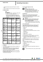
Only strip the cable as far as necessary, ensuring that the cable gland is
sealed and there is no strain on the connections. For tightening torques,
see Chapter 3.1 Product drawing.

NOTE
Tightness and strain relief are dependent on the cable
used.

→ This must be checked by the user.

Fig. 1: Recommended stripped lengths (inside terminal box)
(1) supply line (2) control and relay line

4.3.2 Terminal connection data

Supply line

min.

max.

Rigid cable cross-
section

0.2 mm²

4 mm²

Flexible cable cross-
section

0.2 mm²

4 mm²

AWG/kcmil cable
cross-section

24

12

Wire-end ferrules with
insulating collar,
in accordance with
DIN 46228-4 for
flexible cable

0.25 mm²

4 mm²

Wire-end ferrules
without insulating
collar,
in accordance with
DIN 46228-1 for
flexible cable

0.25 mm²

4 mm²

NOTE

The cable and cable cross-section must be selected taking into
account the max. starting current of the drive and the type of
cable routing (see Chapter 4.2.2 Supply connection and fuses)

Control and relay cables

min.

max.

Rigid cable cross-
section

0.2 mm²

1.5 mm²

Flexible cable cross-
section

0.2 mm²

1.5 mm²

AWG/kcmil cable
cross-section

24

16

Wire-end ferrules with
insulating collar,
in accordance with
DIN 46228-4 for
flexible cable

0.14 mm²

0.75 mm²

Wire-end ferrules
without insulating
collar,
in accordance with
DIN 46228-1 for
flexible cable

0.25 mm²

1.5 mm²

NOTE
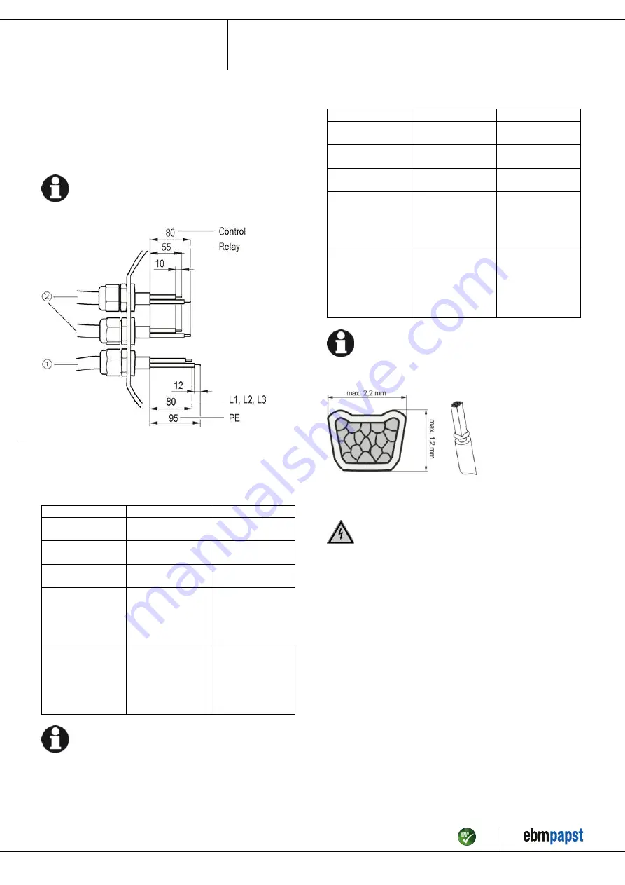
Crimping and pressing forms of the wire-end ferrules

For flexible control and relay cables, from a cable cross-section
of 1.0 mm², a trapezoid crimp is required to ensure correct
installation on the connector.

Fig. 2: Trapezoid crimp

4.3.3 Connect cables to terminals

WARNING
Live terminals and connections even with device
switched off

Electric shock
→ Wait five minutes after disconnecting the voltage at all poles

before opening the device.

;

Open the terminal box.

;

Remove the cap from the cable gland.

;

Only remove caps where cables are fed in.

Item no. 57279-5-9970 · ENU · Change 230632 · Approved 2022-11-16 · Page 9 / 17

ebm-papst Mulfingen GmbH & Co. KG · Bachmühle 2 · D-74673 Mulfingen · Phone +49 (0) 7938 81-0 · Fax +49 (0) 7938 81-110 · info1@de.ebmpapst.com · www.ebmpapst.com

Summary of Contents for R3G310-PV69-03

Page 1: ...specialists are permitted to install the device to carry out a test run and to perform work on the electrical installation 1 3 Basic safety rules 1 1 3 Basic safety rules The safety hazards associated...

Page 2: ...ls occur following installation appropriate shielding measures have to be taken by the user NOTE Electrical or electromagnetic interference after installing the device in customer equipment Verify tha...

Page 3: ...stationary systems Performing all maintenance work Conveying air at an ambient air pressure between 800 mbar and 1050 mbar Using the device within the permitted ambient temperature range see Chapter...

Page 4: ...earance for screw 20 mm 3 Cable diameter min 4 mm max 10 mm tightening torque 4 0 6 Nm The tightening torque is designed for PVC cables If the cable materials are different the tightening torque may h...

Page 5: ...n mm Inlet ring 31475 2 4013 with pressure tap k factor 116 not included in scope of delivery Item no 57279 5 9970 ENU Change 230632 Approved 2022 11 16 Page 5 17 ebm papst Mulfingen GmbH Co KG Bachm...

Page 6: ...n the installation side the ebm papst evaluation loses its validity the conformity must be confirmed again The product does not fall within the scope of Regulation EU 2019 1781 due to the exception sp...

Page 7: ...sibility of the installation engineer or operator owner of the device to ensure if necessary after consultation with the network operator that this device is only connected to a connection point with...

Page 8: ...earth terminal provided on the device The protective earth terminal is located on the housing and provided with a protective earth symbol and a hole 4 2 2 Supply connection and fuses Assignment of sup...

Page 9: ...of the drive and the type of cable routing see Chapter 4 2 2 Supply connection and fuses Control and relay cables min max Rigid cable cross section 0 2 mm 1 5 mm Flexible cable cross section 0 2 mm 1...

Page 10: ...of cables at terminals There must not be any tensile stress between the terminal and the cable gland The cable must be provided with strain relief The cable glands must be tight Fit the terminal box...

Page 11: ...eristic curve P1 IN SELV CON2 IO3 Function parameterizable see Optional interface functions table Factory setting Analog output 0 10 V max 5 mA function Fan modulation level Characteristic curve param...

Page 12: ...159 0 Ain2 0 10V PWM analog input D159 2 Ri 100K characteristic curve parameterizable f PWM 1k 10KHz SELV Ain2 4 20mA analog input Ri 125R characteristic curve parameterizable SELV D159 3 Din3 active...

Page 13: ...operating instructions 4 6 Equivalent circuit diagrams Item no 57279 5 9970 ENU Change 230632 Approved 2022 11 16 Page 13 17 ebm papst Mulfingen GmbH Co KG Bachm hle 2 D 74673 Mulfingen Phone 49 0 793...

Page 14: ...ng Either run through the resonant range as quickly as possible with speed control or find another remedy Operation with excessively high vibration levels can lead to premature failure The maximum per...

Page 15: ...utomatically without warning Faulty connection Isolate from supply correct connection see connection diagram Broken motor winding Replace device Inadequate cooling Improve cooling Allow the device to...

Page 16: ...nsors depends on the device concerned and the installation situation 6 3 Cleaning To ensure a long service life check the fans regularly for proper operation and soiling The frequency of checking is t...

Page 17: ...ns for ecological disposal of the product and its components 6 5 1 Country specific legal requirements NOTE Country specific legal requirements Always observe the applicable country specific legal reg...

Reviews: