background image

Operating instructions

R3G355-RP06-A1

Translation of the original operating instructions

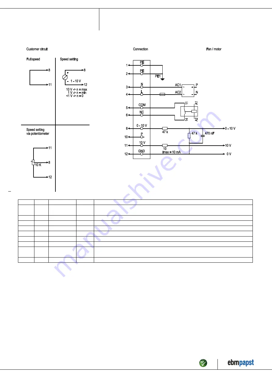
4.5 Connection screen

No.

Conn.

Designation

Colour

Function / assignment

1

1, 2

PE

green/
yellow

Protective earth

1

3

N

blue

Supply voltage, neutral conductor, voltage range see rating plate, 50 / 60 Hz

1

4

L

black

Supply voltage, phase, voltage range see rating plate, 50 / 60 Hz

1

5

COM

white 1

Floating status message contact, normally closed connection (2 A, max. 250 VAC, min. 10 mA)

1

6

NC

white 2

Floating status message contact, normally closed connection

2

8

0 -10 V

yellow

Control input, set value 0 - 10 VDC, impedance 100 kOhm, SELV

2

10

P

orange

Not assigned

2

11

10 VDC

red

Voltage output 10 VDC (+/-3%), max. 10 mA, supply voltage for ext. devices (e.g. potentiometer),
SELV

2

12

GND

blue

Reference mass for control interface, SELV

Item no. 51757-5-9970 · Revision 82546 · Release 2014-05-08 · Page 8 / 11

ebm-papst Mulfingen GmbH & Co. KG · Bachmühle 2 · D-74673 Mulfingen · Phone +49 (0) 7938 81-0 · Fax +49 (0) 7938 81-110 · info1@de.ebmpapst.com · www.ebmpapst.com

Summary of Contents for R3G355-RP06-A1

Page 1: ...permitted to install the device to carry out a test run and to perform work on the electrical installation 1 3 Basic safety rules 1 1 3 Basic safety rules Any safety hazards stemming from the device m...

Page 2: ...t the entire setup is EMC compliant 1 7 Mechanical movement DANGER Rotating device Body parts that come into contact with the rotor and impeller can be injured Secure the device against accidental con...

Page 3: ...the following ways is particularly prohibited and may cause hazards Operating the device with an imbalance e g caused by dirt deposits or icing Moving air that contains abrasive particles Moving highl...

Page 4: ...00 2 4013 not included in scope of delivery 2 Depth of screw max 10 mm 3 Connection line PVC AWG18 5x crimped core end sleeves 4 Connection line PVC AWG22 3x crimped core end sleeves Item no 51757 5 9...

Page 5: ...ut 10 VDC max 10 mA Alarm relay Motor current limit PFC active Soft start Control input 0 10 VDC PWM Control interface with SELV potential safely disconnected from the mains Over temperature protected...

Page 6: ...g the device ensure that the supply voltage matches the operating voltage of the device Only use cables designed for current according to the type plate For determining the cross section follow the ba...

Page 7: ...5 Connection screen 4 4 Factory settings Factory settings with which the device is pre set by ebm papst Operation mode PWM controlling Group adress 01 Fan device adress 01 Max PWM 84 Min PWM 0 Save s...

Page 8: ...ct normally closed connection 2 A max 250 VAC min 10 mA 1 6 NC white 2 Floating status message contact normally closed connection 2 8 0 10 V yellow Control input set value 0 10 VDC impedance 100 kOhm...

Page 9: ...ignal 4 8 Switching off the device Switching off the device during operation Switch off the device via the control input Do not switch the motor e g in cyclic operation on and off via power supply Swi...

Page 10: ...ector responded Allow motor to cool off locate and rectify cause of error if necessary cancel restart lock out Overtemperature of electronics motor Insufficient cooling Improve cooling Let the device...

Page 11: ...the wires for damage Visual inspection At least every 6 months Replace wires Impeller for wear deposits corrosion and damage Visual inspection At least every 6 months Clean or replace impeller Item n...

Reviews: