


Operating instructions
R3G450-PA31-02
Translation of the original operating instructions
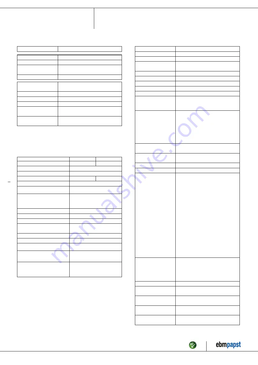
3.2 Nominal data
Motor
M3G150-FF
Phase
3~
Nominal voltage / VAC
400
Nominal voltage
range / VAC
380 .. 480
Frequency / Hz
50/60
Method of obtaining
data
ml
Speed (rpm) / min
-1
2480
Power consumption / W
4450
Current draw / A
6.8
Min. ambient
temperature / °C
-40
Max. ambient
temperature / °C
40
ml = Max. load · me = Max. efficiency · fa = Free air
cs = Customer specification · ce = Customer equipment
Subject to change
3.3 Data according to Commission Regulation (EU) 327/
2011
Actual
Req. 2015
01 Overall efficiency η
es
/ %
69.3
58.3
02 Measurement category
A
03 Efficiency category
Static
04 Efficiency grade N
73
62
05 Variable speed drive
Yes
06 Year of manufacture
The year of manufacture is specified on the
product's rating label.
07 Manufacturer
ebm-papst Mulfingen GmbH & Co. KG
Amtsgericht (court of registration) Stuttgart ·
HRA 590344
D-74673 Mulfingen
08 Type
R3G450-PA31-02
09 Power consumption P
ed
/ kW
4.47
09 Air flow q
v
/ m³/h
8450
09 Pressure increase total p
fs
/
Pa
1275
10 Speed (rpm) n / min
-1
2460
11 Specific ratio
*
1.01
12 Recycling/disposal
Information on recycling and disposal is
provided in the operating instructions.
13 Maintenance
Information on installation, operation and
maintenance is provided in the operating
instructions.
14 Additional components
Components used to calculate the energy
efficiency that are not apparent from the
measurement category are detailed in the
CE declaration.
*
Specific ratio = 1 + p
fs
/ 100 000 Pa
Data obtained at optimum efficiency level. The efficiency values displayed for achieving
conformity with the Ecodesign Regulation EU 327/2011 has been reached with defined air
duct components (e.g. inlet rings). The dimensions must be requested from ebm-papst. If
other air conduction geometries are used on the installation side, the ebm-papst evaluation
loses its validity/the conformity must be confirmed again. The product does not fall within
the scope of Regulation (EU) 2019/1781 due to the exception specified in Article 2 (2a)
(motors completely integrated into a product).
3.4 Technical description
Size
450 mm
Motor size
150
Rotor surface
Painted black
Electronics housing
material
Die-cast aluminum
Impeller material
Sheet aluminum
Number of blades
5
Direction of rotation
Clockwise, viewed toward rotor
Degree of protection
IP55
Insulation class
"F"
Moisture (F) /
Environmental (H)
protection class
H1
Ambient temperature
note
Occasional start-up at temperatures
between -40°C and -25°C is permitted.
For continuous operation at ambient
temperatures below -25°C (such as
refrigeration applications), use must be
made of a fan design with special low-
temperature bearings.
Installation position
Shaft horizontal or rotor on bottom; rotor
on top on request
Condensation
drainage holes
On rotor side
Mode
S1
Motor bearing
Ball bearing
Technical features
- Operation and alarm display with LED
- External 15-50 VDC input
(parameterization)
- Alarm relay
- Integrated PI controller
- Configurable inputs/outputs (I/O)
- MODBUS V6.3
- Motor current limitation
- RS-485 MODBUS-RTU
- Soft start
- Voltage output 3.3-24 VDC, Pmax =
800 mW
- Control interface with SELV potential
safely disconnected from the mains
- Thermal overload protection for
electronics/motor
- Line undervoltage / phase failure
detection
Touch current
according to IEC
60990 (measuring
circuit Fig. 4, TN
system)
<= 3.5 mA
Electrical hookup
Terminal box
Motor protection
Reverse polarity and locked-rotor
protection
Protection class
I (with customer connection of protective
earth)
Conformity with
standards
EN 61800-5-1; CE
Approval
CSA C22.2 No. 77 + CAN/CSA-
E60730-1; EAC; UL 1004-7 + 60730-1
Item no. 57456-5-9970 · ENU · Change 219784 · Approved 2020-09-18 · Page 6 / 17
ebm-papst Mulfingen GmbH & Co. KG · Bachmühle 2 · D-74673 Mulfingen · Phone +49 (0) 7938 81-0 · Fax +49 (0) 7938 81-110 · info1@de.ebmpapst.com · www.ebmpapst.com


