background image

Operating instructions
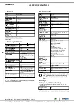
R3G500-RH32-25

Translation of the original operating instructions

→ Wait five minutes after disconnecting the voltage at all poles

before opening the device.

CAUTION
In the event of a fault, the rotor and the impeller will be
energized

The rotor and the impeller have basic insulation.
→ Do not touch the rotor and impeller once installed.

CAUTION
If control voltage or a stored speed set value is applied,
the motor will restart automatically, e.g. after a power
failure.

Risk of injury
→ Keep out of the device danger zone.
→ When working on the device, switch off the line voltage

and ensure that it cannot be switched back on.

→ After working on the device, remove any tools or other

objects from the device.

1.5 Safety and protective features

DANGER
Protective device missing and protective device not
functioning

Without a protective device there is a risk of serious injury, for
instance if the hands reach or are sucked into the device during
operation.
→ Operate the device only with a fixed protective device and

guard grille.# The fixed protective device must be able to
withstand the kinetic energy of a fan blade that becomes
detached at maximum speed. There must not be any gaps
which it is possible to reach into with the fingers, for example.

→ The device is a built-in component. As the operator, you

are responsible for ensuring that the device is secured
adequately.

→ Stop the device immediately if you notice a missing or

ineffective protective device.

1.6 Electromagnetic radiation

Interference from electromagnetic radiation is possible, e.g. in conjunction
with open- and closed-loop control devices.
If impermissible radiation levels occur following installation, appropriate
shielding measures have to be taken by the user.

NOTE
Electrical or electromagnetic interference after installing
the device in customer equipment.

→ Verify that the entire setup is EMC-compliant.

1.7 Mechanical movement

DANGER
Rotating device

Risk of injury to body parts coming into contact with the rotor or
the impeller.
→ Secure the device against accidental contact.
→ Before working on the system/machine, wait until all

parts have come to a standstill.

DANGER
Ejected parts

Missing protective devices may cause balancing weights or
broken fan blades to be ejected and cause injuries.
→ Take appropriate safety measures.

WARNING
Rotating device

Long hair and dangling items of clothing, jewelry and the like
can become entangled and be pulled into the device. Injuries
can result.
→ Do not wear any loose-fitting or dangling clothing or jewelry

while working on rotating parts.#Protect long hair with a cap.

1.8 Emissions

WARNING
Depending on the installation and operating conditions,
the sound pressure level may exceed 70 dB(A).

Risk of noise-induced hearing loss
→ Take appropriate technical safety measures.
→ Protect operating personnel with appropriate safety

equipment such as hearing protection.

→ Also observe the requirements of local agencies.

1.9 Hot surface

CAUTION
High temperature on electronics housing

Risk of burns
→ Ensure sufficient protection against accidental contact.

1.10 Storage

;

Store the device, partially or fully assembled, in a dry and
weatherproof manner in the original packaging in a clean environment.

;

Protect the device against environmental effects and dirt until final
installation.

;

We recommend storing the device for no longer than one year in
order to guarantee trouble-free operation and the longest possible
service life.

;

Even devices explicitly intended for outdoor use are to be stored as
described prior to commissioning.

;

Maintain the storage temperature, see
Chapter 3.6 Transport and storage conditions.

Item no. 51228-5-9970 · ENU · Change 89187 · Approved 2016-04-15 · Page 2 / 11

ebm-papst Mulfingen GmbH & Co. KG · Bachmühle 2 · D-74673 Mulfingen · Phone +49 (0) 7938 81-0 · Fax +49 (0) 7938 81-110 · info1@de.ebmpapst.com · www.ebmpapst.com

Summary of Contents for R3G500-RH32-25

Page 1: ...sed by suitably qualified trained and authorized technical staff Only authorized specialists are permitted to install the device to carry out a test run and to perform work on the electrical installation 1 3 Basic safety rules 1 1 3 Basic safety rules The safety hazards associated with the device must be assessed again following installation in the final product Note the following when working on ...

Page 2: ...ice in customer equipment Verify that the entire setup is EMC compliant 1 7 Mechanical movement DANGER Rotating device Risk of injury to body parts coming into contact with the rotor or the impeller Secure the device against accidental contact Before working on the system machine wait until all parts have come to a standstill DANGER Ejected parts Missing protective devices may cause balancing weig...

Page 3: ...ar operating the device in the following ways is prohibited and could be hazardous Operating the device in an unbalanced state e g due to dirt deposits or ice formation Operation in medical equipment with a life sustaining or life support function Operation with external vibrations Conveying solids in the flow medium Painting the device Connections e g screws coming loose during operation Conveyin...

Page 4: ...Inlet ring 50901 2 2943 not included in scope of delivery 2 Clearance for screw 12 16 mm 3 Cable AWG 18 5x crimped splices 4 Cable AWG 22 4x crimped splices Item no 51228 5 9970 ENU Change 89187 Approved 2016 04 15 Page 4 11 ebm papst Mulfingen GmbH Co KG Bachmühle 2 D 74673 Mulfingen Phone 49 0 7938 81 0 Fax 49 0 7938 81 110 info1 de ebmpapst com www ebmpapst com ...

Page 5: ...eller combination in a standardized measurement setup 3 4 Technical description Weight 13 1 kg Fan size 500 mm Rotor surface Painted black Electronics housing material Die cast aluminum Impeller material PP plastic Number of blades 7 Direction of rotation Clockwise viewed toward rotor Degree of protection IP54 Insulation class B Moisture F Environmental H protection class F4 1 Installation positio...

Page 6: ...ly and PE connections CAUTION Voltage The fan is a built in component and has no disconnecting switch Only connect the fan to circuits that can be switched off with an all pole disconnection switch When working on the fan secure the system machine in which the fan is installed so as to prevent it from being switched back on NOTE Water ingress into wires or cables Water ingress at the customer end ...

Page 7: ... connect the PE protective earth Connect the cables according to your application When doing so observe Chapter 4 5 Connection diagram 4 4 Factory settings Factory settings made for the device by ebm papst Mode PWM control Group address 1 Fan device address 1 Max PWM 100 Min PWM 0 Save set value to EEPROM Yes Set value requirement Analog Direction of action Positive heating Item no 51228 5 9970 EN...

Page 8: ...reak for failure 2 A max 250 VAC min 10 mA AC1 1 6 NC white 2 Floating status contact break for failure 2 8 0 10 V yellow Control input set value 0 10 VDC impedance 100 kΩ SELV 2 11 10 VDC red Voltage output 10 VDC 3 max 10 mA power supply for external devices e g potentiometer SELV 2 12 GND blue Reference ground for control interface SELV Item no 51228 5 9970 ENU Change 89187 Approved 2016 04 15 ...

Page 9: ...tion detection error An automatic restart follows Blocked rotor After the blockage is removed the motor restarts automatically Line undervoltage line voltage outside of permitted nominal voltage range If the line voltage returns to permitted values the motor restarts automatically 6 MAINTENANCE MALFUNCTIONS POSSIBLE CAUSES AND REMEDIES Do not perform any repairs on your device Send the device to e...

Page 10: ...ate goals ebm papst operates an environmental management system which is certified in accordance with ISO 14001 and rigorously implemented around the world on the basis of German standards Right from the development stage ecological design technical safety and health protection are fixed criteria The following section contains recommendations for ecological disposal of the product and its componen...

Page 11: ...or internal wiring Electrolytic capacitors Dispose of electronic components employing the proper procedures for electronic scrap Please contact ebm papst for any other questions on disposal Item no 51228 5 9970 ENU Change 89187 Approved 2016 04 15 Page 11 11 ebm papst Mulfingen GmbH Co KG Bachmühle 2 D 74673 Mulfingen Phone 49 0 7938 81 0 Fax 49 0 7938 81 110 info1 de ebmpapst com www ebmpapst com...

Reviews: