
Operating instructions
R3G560-RA25-71
Translation of the original operating instructions
4.6 Checking the connections
;
Make sure that the power is off (all phases).
;
Secure it from being switched on again.
;
Check the correct fit of the connection lines.
;
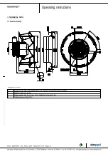
Screw the terminal box cover closed again. Terminal box tightening
torque, see chapter 3.1 Product drawing.
;
Route the connecting cables in the terminal box so that the terminal
box cover closes without resistance.
;
Use all plug screws (the entire number). In doing so, insert the
screws manually to avoid damage to the thread.
;
Make sure that the terminal box is correctly closed and sealed and
that all screws and screwed cable glands are properly tightened.
4.7 Switch on device
The device may only be switched on if it has been installed properly and
in accordance with its intended use, including the required safety
mechanisms and professional electrical connection. This also applies for
devices which have already been equipped with plugs and terminals or
similar connectors by the customer.
WARNING
Hot motor housing
Fire hazard
→ Ensure that no combustible or flammable materials are
located close to the fan.
;
Inspect the device for visible external damage and the proper function
of the protective features before switching it on.
;
Check the air flow paths of the fan for foreign objects and remove any
that are found.
;
Apply the nominal voltage to the voltage supply.
;
Start the device by changing the input signal.
4.8 Switching off the device
Switching off the device during operation:
;
Switch off the device via the control input.
;
Do not switch the motor (e.g. in cyclic operation) on and off via power
supply.
Switching off the device for maintenance work:
;
Switch off the device via the control input.
;
Do not switch the motor (e.g. in cyclic operation) on and off via power
supply.
;
Disconnect the device from the supply voltage.
;
When disconnecting, be sure to disconnect the earth wire connection
last.
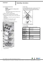
5. INTEGRATED PROTECTIVE FUNCTIONS
The integrated protective functions cause the motor to switch off
automatically in case of faults described in the table.
Malfunctions
Description / Function of
safety feature
Rotor position detection error
An automatic restart occurs.
Locked rotor
;
After the blockage is
removed, the motor restarts
automatically.
Line under-voltage (mains input
voltage outside of permitted
nominal voltage)
;
If the mains supply voltage
returns to permitted values, the
motor restarts automatically.
Phase failure
A phase of the supply voltage
fails for at least 5 s.
;
If all phases are correctly
supplied again, the motor
automatically restarts after 10 -
40 s.
Item no. 52299-5-9970 · ENG · Revision 82270 · Release 2014-11-28 · Page 10 / 12
ebm-papst Mulfingen GmbH & Co. KG · Bachmühle 2 · D-74673 Mulfingen · Phone +49 (0) 7938 81-0 · Fax +49 (0) 7938 81-110 · info1@de.ebmpapst.com · www.ebmpapst.com


