background image

Operating instructions

R3G560-RA25-71

Translation of the original operating instructions

4.3.2 Connecting cables with terminals

WARNING
Terminals and connections have voltage even with a
unit that is shut off

Electric shock
→ Wait five minutes after disconnecting the voltage at all poles

before opening the device.

;

Remove the cap from the screwed cable gland.

Remove the cap only in those places where cables are inserted.

;

Mount the screwed cable glands with the seal inserts provided in the
terminal box.

;

Insert the line(s) (not included in the standard scope of delivery) into
the terminal box.

;

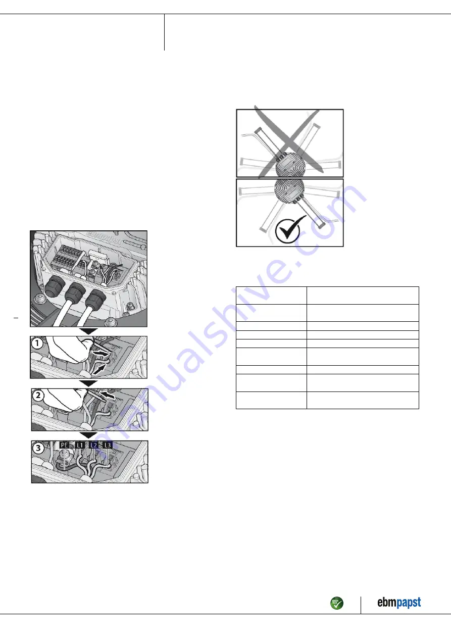
First connect the "PE" (protective earth) connection.

;

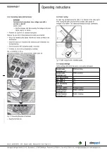
Connect the lines to the corresponding terminals.

Use a screwdriver to do so.
During the connection work, ensure that no cables splice off.

Fig. 2: Connecting the wires to terminals

;

Seal the terminal box.
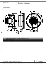
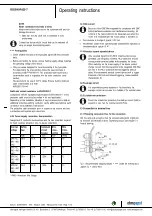
4.3.3 Cable routing

No water may penetrate along the cable in the direction of the cable gland.
When routing the cable, ensure that the screwed cable glands are
arranged at the bottom. The cables must always be routed downwards.

Fig. 3: Cable routing for fans installed upright.

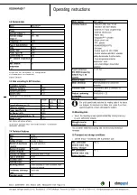
4.4 Factory settings

Factory settings with which the device is pre-set by ebm-papst.

Control mode
parameter set 1

PWM controlling

Control mode
parameter set 2

PWM controlling

Fan / device adress

1

Max. PWM / %

100

Min. PWM / %

5,1

Save set value to
EEPROM

Yes

Set value control

Analogue (linear)

Control function
parameter set 1

Positive (heating)

Control function
parameter set 2

Positive (heating)

Item no. 52299-5-9970 · ENG · Revision 82270 · Release 2014-11-28 · Page 8 / 12

ebm-papst Mulfingen GmbH & Co. KG · Bachmühle 2 · D-74673 Mulfingen · Phone +49 (0) 7938 81-0 · Fax +49 (0) 7938 81-110 · info1@de.ebmpapst.com · www.ebmpapst.com

Summary of Contents for R3G560-RA25-71

Page 1: ...to carry out a test run and to perform work on the electrical installation 1 3 Basic safety rules 1 1 3 Basic safety rules Any safety hazards stemming from the device must be re evaluated once it is...

Page 2: ...on the system machine wait until all parts have come to a standstill DANGER Flying parts Missing safety devices may cause balancing weights or broken fan blades to be ejected at high speeds causing bo...

Page 3: ...hazards Operating the device with an imbalance e g caused by dirt deposits or icing Operation in medical equipment with a life sustaining or lifesaving function Operation with external vibrations Mov...

Page 4: ...82 2 4013 not included in the standard scope of delivery 2 Depth of screw max 25 mm 3 Cable diameter min 4 mm max 10 mm tightening torque 4 0 6 Nm 4 Tightening torque 3 5 0 5 Nm Item no 52299 5 9970 E...

Page 5: ...Rotor side Operation mode S1 Motor bearing Ball bearing Technical features Output 10 VDC max 10 mA Operation and alarm display External 24 V input programming External release input Alarm relay Integr...

Page 6: ...s must no longer be installed Install the undamaged device according to your application 4 2 Connecting the electrical system DANGER Electric voltage on the device Electric shock Always install a prot...

Page 7: ...AC 16 A 15 A C16A 1 5 16 3 PE AC 380 480 VAC 20 A 20 A C20A 2 5 14 3 PE AC 380 480 VAC 25 A 25 A C25A 4 0 12 3 PE AC 380 480 VAC 32 A 30 A C32A 6 0 10 AWG American Wire Gauge 4 2 3 Idle current Becaus...

Page 8: ...at no cables splice off Fig 2 Connecting the wires to terminals Seal the terminal box 4 3 3 Cable routing No water may penetrate along the cable in the direction of the cable gland When routing the ca...

Page 9: ...ver contact common connection contact rating 250 VAC 2 A AC1 KL 2 5 Din1 Digital input 1 enabling of electronics enabling open pin or applied voltage 5 50 VDC disabling bridge to GND or applied voltag...

Page 10: ...fan for foreign objects and remove any that are found Apply the nominal voltage to the voltage supply Start the device by changing the input signal 4 8 Switching off the device Switching off the devi...

Page 11: ...Switch off de energise and remove mechanical blockage Mains supply voltage faulty Check mains supply voltage restore power supply Important The error message resets automatically The device starts up...

Page 12: ...nst accidental contact for damage and to ensure that it is intact Visual inspection At least every 6 months Repair or replacement of the device Check the device for damage to blades and housing Visual...

Reviews: