


Operating instructions
R4D310-AR18-01
Translation of the original operating instructions
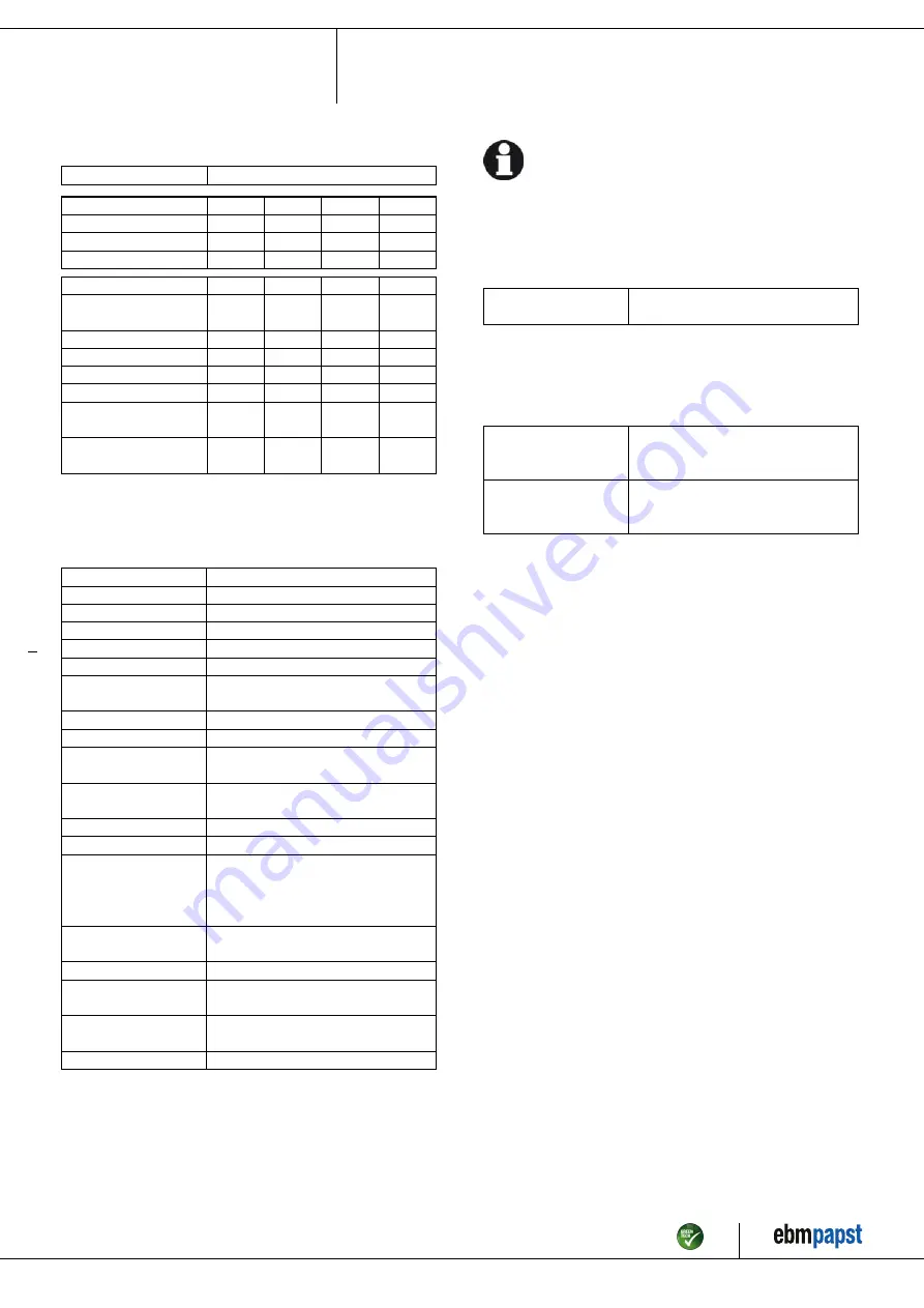
3.2 Nominal data
Motor
M4D068-EC
Phase
3~
3~
3~
3~
Nominal voltage / VAC
230
230
400
400
Connection
Δ
Δ
Y
Y
Frequency / Hz
50
60
50
60
Type of data definition
fa
fa
fa
fa
Valid for approval /
standard
CE
CE
CE
CE
Speed / min
-1
1430
1650
1430
1650
Power input / W
85
115
85
115
Current draw / A
0.52
0.45
0.3
0.26
Min. back pressure / Pa
0
0
0
0
Min. ambient
temperature / °C
-25
-25
-25
-25
Max. ambient
temperature / °C
75
80
75
80
ml = max. load · me = max. efficiency · fa = running at free air
cs = customer specs · cu = customer unit
Subject to alterations
3.3 Technical features
Mass
3.6 kg
Size
310 mm
Surface of rotor
Coated in black
Material of impeller
Aluminum sheet, laser-welded
Number of blades
6
Direction of rotation
Clockwise, seen on rotor
Type of protection
IP 44; Depending on installation and
position as per EN 60034-5
Insulation class
"B"
Humidity class
F1-2
Mounting position
Shaft horizontal or rotor on bottom; rotor
on top on request
Condensate discharge
holes
Rotor-side
Operation mode
S1
Motor bearing
Ball bearing
Touch current acc.
IEC 60990 (measuring
network Fig. 4, TN
system)
< 0.75 mA
Motor protection
Thermal overload protector (TOP)
brought out
Cable exit
Axial
Protection class
I (if protective earth is connected by
customer)
Product conforming
to standard
EN 60335-1; CE
Approval
CCC
For cyclic speed loads, note that the rotating parts of the device
are designed for maximum one million load cycles. If you have
specific questions, contact ebm-papst for support.
3.4 Mounting data
For depth of screw, see chapter 3.1 Product drawing
;
Secure the mounting screws against accidentally coming loose (e.g.
by using self-locking screws).
Strength class for
mounting screws
8.8
You can obtain additional mounting data from the product drawing if
necessary.
3.5 Transport and storage conditions
;
Use the device in accordance with its protection type.
Max. permissible
ambient motor temp.
(transp./ storage)
+ 80 °C
Min. permissible
ambient motor temp.
(transp./storage)
- 40 °C
Item no. 11501-5-9970 · Revision 73571 · Release 2011-04-13 · Page 5 / 9
ebm-papst Mulfingen GmbH & Co. KG · Bachmühle 2 · D-74673 Mulfingen · Phone +49 (0) 7938 81-0 · Fax +49 (0) 7938 81-110 · info1@de.ebmpapst.com · www.ebmpapst.com


