


Operating instructions
R4D355-RB10-01
Translation of the original operating instructions
3. TECHNICAL DATA
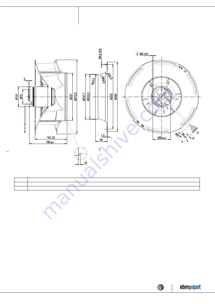
3.1 Product drawing
All measures have the unit mm.
1
Accessory part: Inlet nozzle 35500-2-4013, not included in the standard scope of delivery
2
Depth of screw max. 10 mm
3
Connection line silicone 9G 0.5 mm², 9x brass lead tips crimped
Item no. 12188-5-9970 · Revision 79663 · Release 2013-04-24 · Page 4 / 10
ebm-papst Mulfingen GmbH & Co. KG · Bachmühle 2 · D-74673 Mulfingen · Phone +49 (0) 7938 81-0 · Fax +49 (0) 7938 81-110 · info1@de.ebmpapst.com · www.ebmpapst.com


