Operating instructions
R4E250-CG01-01
Translation of the original operating instructions
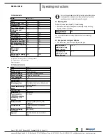
3. TECHNICAL DATA
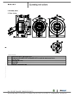
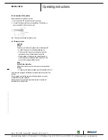
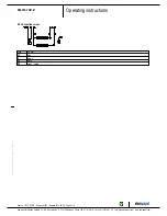
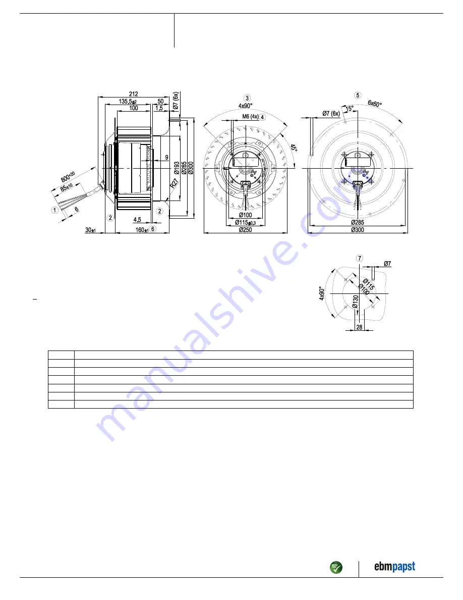
3.1 Product drawing
All measures have the unit mm.
1
Connection line silicone, 6 x brass lead tips crimped
2
Accessory part: Inlet nozzle 25010-2-4013 and flange 94250-2-4017 not included in the standard scope of delivery
3
View without flange
4
Depth of screw max. 12 mm
5
View with flange
6
Housing width
7
Drill pattern for mounting without flange
Item no. 10715-5-9970 · Revision 82542 · Release 2014-05-08 · Page 4 / 10
ebm-papst Mulfingen GmbH & Co. KG · Bachmühle 2 · D-74673 Mulfingen · Phone +49 (0) 7938 81-0 · Fax +49 (0) 7938 81-110 · info1@de.ebmpapst.com · www.ebmpapst.com


