background image

Operating instructions

S3G250-BC54-01

Translation of the original operating instructions
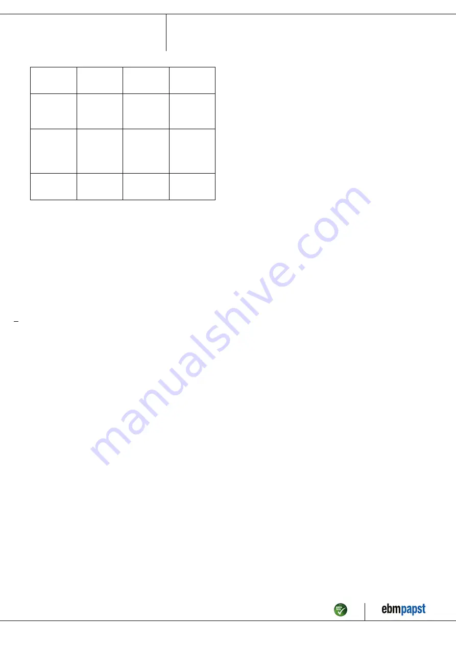
Mounting of
protective
earth connection

Visual inspection At least every

6 months

Fasten

Check the
insulation of
the wires for
damage

Visual inspection At least every

6 months

Replace wires

Condensate
discharge
holes for
clogging, as
necessary

Visual inspection At least every

6 months

Open bore holes

Weld seams
for crack
formation

Visual inspection At least every

6 months

Replace device

Item no. 50334-5-9970 · Revision 82795 · Release 2014-05-08 · Page 10 / 10

ebm-papst Mulfingen GmbH & Co. KG · Bachmühle 2 · D-74673 Mulfingen · Phone +49 (0) 7938 81-0 · Fax +49 (0) 7938 81-110 · info1@de.ebmpapst.com · www.ebmpapst.com

Summary of Contents for S3G250-BC54-01

Page 1: ...cialists are permitted to install the device to carry out a test run and to perform work on the electrical installation 1 3 Basic safety rules 1 1 3 Basic safety rules Any safety hazards stemming from...

Page 2: ...t the entire setup is EMC compliant 1 7 Mechanical movement DANGER Rotating device Body parts that come into contact with the rotor and impeller can be injured Secure the device against accidental con...

Page 3: ...the following ways is particularly prohibited and may cause hazards Operating the device with an imbalance e g caused by dirt deposits or icing Moving air that contains abrasive particles Moving highl...

Page 4: ...unit mm 1 Direction of air flow V 2 Connection line AWG 18 3x female connector crimped 3 Connection line AWG 22 4x female connector crimped Item no 50334 5 9970 Revision 82795 Release 2014 05 08 Page...

Page 5: ...on top on request Condensate discharge holes Rotor side Operation mode S1 Motor bearing Ball bearing Technical features Control input 0 10 VDC PWM Output 10 VDC max 1 1 mA Tach output Over temperatur...

Page 6: ...of the device Only use cables designed for current according to the type plate For determining the cross section follow the basic principles in accordance with EN 61800 5 1 The protective earth must h...

Page 7: ...rth 8 0 10 V PWM yellow Control input 0 10 V or PWM electrically isolated 9 Tach white Tach output open collector 1 pulse per revolution electrically isolated 11 10V max 1 1 mA red Voltage output 10 V...

Page 8: ...the nominal voltage to the voltage supply Start the device by changing the input signal 4 7 Switching off the device Switching off the device during operation Switch off the device via the control inp...

Page 9: ...tector responded Allow motor to cool off locate and rectify cause of error if necessary cancel restart lock out Overtemperature of electronics motor Insufficient cooling Improve cooling Let the device...

Page 10: ...least every 6 months Replace wires Condensate discharge holes for clogging as necessary Visual inspection At least every 6 months Open bore holes Weld seams for crack formation Visual inspection At l...

Reviews: