background image

Operating instructions

S4E500-ZL07-01

Translation of the original operating instructions

DANGER
Faulty insulation

Risk of fatal injury from electric shock
→ Use only cables that meet the specified installation

regulations for voltage, current, insulation material, capacity,
etc.

→ Route cables so that they cannot be touched by any

rotating parts.

DANGER
Electrical charge (>50 µC) between phase conductor and
protective earth connection after switching off supply
with multiple devices connected in parallel.

Electric shock, risk of injury
→ Ensure sufficient protection against accidental contact.

Before working on the electrical hookup, short the supply
and PE connections.

CAUTION
Voltage

The fan is a built-in component and has no disconnecting switch.
→ Only connect the fan to circuits that can be switched off with

an all-pole disconnection switch.

→ When working on the fan, secure the system/machine in

which the fan is installed so as to prevent it from being
switched back on.

NOTE
Water ingress into wires or cables

Water ingress at the customer end of the cable can damage the
device.
→ Make sure the end of the cable is connected in a dry

environment.

Only connect the device to circuits that can be switched off with
an all-pole disconnection switch.

4.2.1 Requirements

;

Check whether the information on the nameplate matches the
connection data.

;

If the motor run capacitor was not installed by ebm-papst, check
whether the information on the motor run capacitor matches the
information on the nameplate.

;

Before connecting the device, make sure the power supply matches
the device voltage.

;

Only use cables designed for the current level indicated on the
nameplate.
For determining the cross-section, note the sizing criteria according
to EN 61800-5-1. The protective earth must have a cross-section
equal to or greater than that of the phase conductor.
We recommend the use of 105 °C cables. Ensure that the minimum
cable cross-section is at least
AWG 26 / 0.13 mm².

4.2.2 Residual current circuit breaker (RCCB)

If the use of a residual current device (RCD) is required in your
installation, only pulse-current sensitive and/or AC/DC-
sensitive residual current devices (type A or B) are
permissible. As with variable frequency drives, residual current
devices cannot provide personal safety while operating the
device.

4.2.3 Voltage control

NOTE

Current overshoots may occur if speed control is implemented
by transformers or electronic voltage regulators (e.g. phase
control). Depending on the type of installation of the device,
noise and vibration may also occur in the case of phase
control. Vibration can lead to bearing damage and thus
premature failure.

Heating-up of the motor when using voltage control must be checked by
the customer following installation in the end device.

4.2.4 Variable frequency drive

Please use a variable frequency drive only after consultation with ebm-
papst.

For operation with variable frequency drives, install sinusoidal
filters that work on all poles (phase-phase and phase-ground)
between the drive and the motor.
During operation with variable frequency drives, an all-pole
sine filter protects the motor against high-voltage transients that
can destroy the coil insulation system, and against harmful
bearing currents.

Heating-up of the motor when using a variable frequency drive must be
checked by the customer following installation in the end device.

4.3 Connection in terminal box

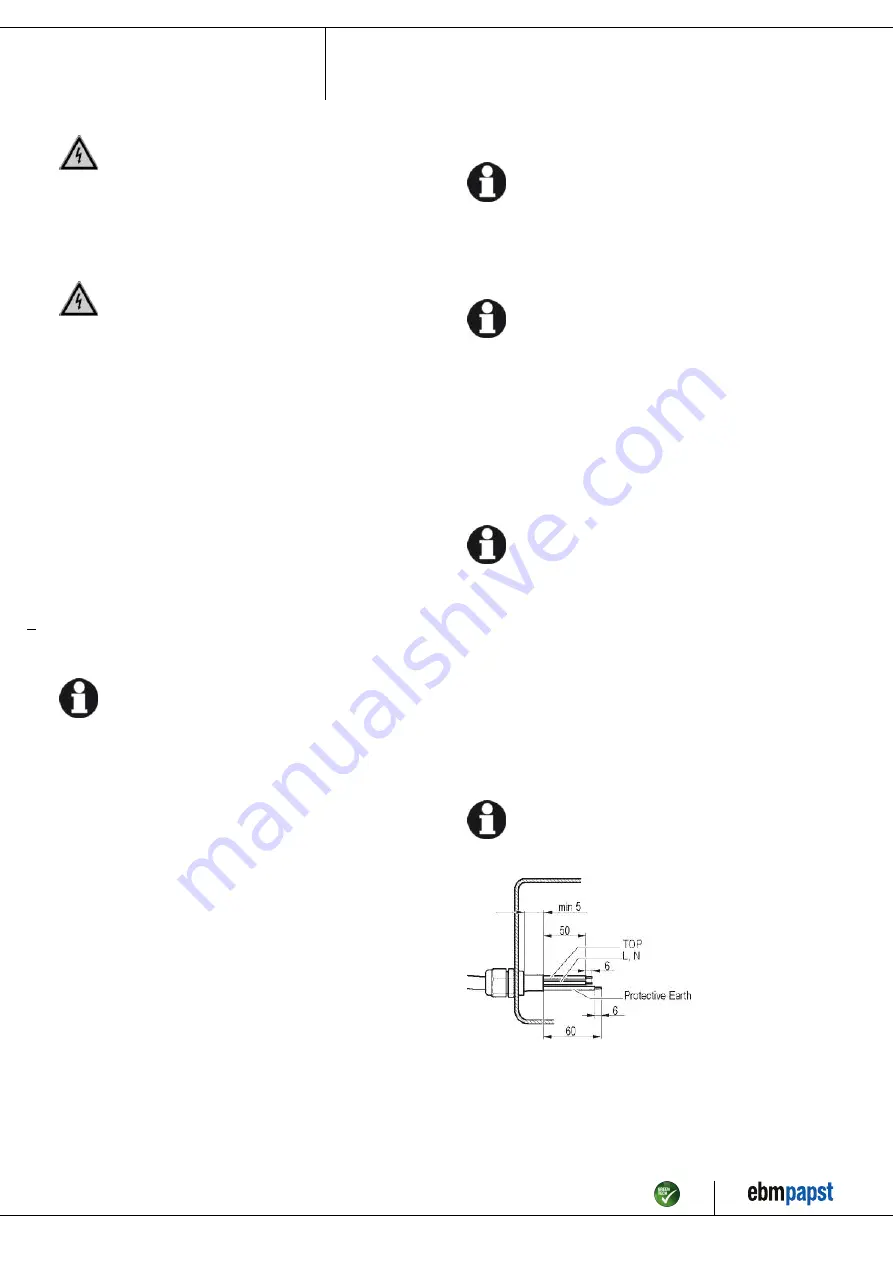
4.3.1 Preparing cables for connection

Only strip the cable as far as necessary, ensuring that the cable gland is
sealed and there is no strain on the connections. For tightening torques,
see Chapter 3.1 Product drawing.

NOTE
Tightness and strain relief are dependent on the cable
used.

→ This must be checked by the user.

Item no. 17064-5-9970 · ENU · Change 231171 · Approved 2021-04-28 · Page 8 / 13

ebm-papst Mulfingen GmbH & Co. KG · Bachmühle 2 · D-74673 Mulfingen · Phone +49 (0) 7938 81-0 · Fax +49 (0) 7938 81-110 · info1@de.ebmpapst.com · www.ebmpapst.com

Summary of Contents for S4E500-ZL07-01

Page 1: ...authorized technical staff Only authorized specialists are permitted to install the device to carry out a test run and to perform work on the electrical installation 1 3 Basic safety rules 1 1 3 Basic safety rules The safety hazards associated with the device must be assessed again following installation in the final product The locally applicable industrial safety regulations are always to be obs...

Page 2: ... grill There must be sufficient space around the fan to be able to get past the fan 1 6 Mechanical movement DANGER Rotating device Risk of injury to body parts coming into contact with the rotor or the impeller Secure the device against accidental contact Before working on the system machine wait until all parts have come to a standstill WARNING Rotating device Long hair and dangling items of clot...

Page 3: ...e hazardous Operating the device in an unbalanced state e g due to dirt deposits or ice formation Resonant operation operation with severe vibration This also includes vibration transmitted to the fan from the customer installation Operation in medical equipment with a life sustaining or life support function Conveying solids in the flow medium Painting the device Connections e g screws coming loo...

Page 4: ...ghtening torque 1 5 0 2 Nm 3 Cable diameter min 6 mm max 12 mm tightening torque 2 0 3 Nm 4 Accessory part Inlet ring 50100 2 4013 not included in scope of delivery Item no 17064 5 9970 ENU Change 231171 Approved 2021 04 28 Page 4 13 ebm papst Mulfingen GmbH Co KG Bachmühle 2 D 74673 Mulfingen Phone 49 0 7938 81 0 Fax 49 0 7938 81 110 info1 de ebmpapst com www ebmpapst com ...

Page 5: ...ting instructions All dimensions in mm Inlet ring 50100 2 4013 Item no 17064 5 9970 ENU Change 231171 Approved 2021 04 28 Page 5 13 ebm papst Mulfingen GmbH Co KG Bachmühle 2 D 74673 Mulfingen Phone 49 0 7938 81 0 Fax 49 0 7938 81 110 info1 de ebmpapst com www ebmpapst com ...

Page 6: ...um efficiency level The ErP data is determined using a motor impeller combination in a standardized measurement setup 3 4 Technical description Size 500 mm Motor size 110 Rotor surface Painted black Terminal box material PP plastic Impeller material PP plastic galvanized sheet metal plate Guard grille material Steel coated with black plastic RAL 9005 Number of blades 5 Airflow direction V Directio...

Page 7: ...he fan on a soft surface Make sure the blades are not subjected to load Following installation make sure the impeller moves easily and that the blades of the impeller are not deformed or bent and do not catch at any point NOTE Damage to the device from vibration Bearing damage shorter service life The fan must not be subjected to force or excessive vibration from sections of the installation If th...

Page 8: ...e of 105 C cables Ensure that the minimum cable cross section is at least AWG 26 0 13 mm 4 2 2 Residual current circuit breaker RCCB If the use of a residual current device RCD is required in your installation only pulse current sensitive and or AC DC sensitive residual current devices type A or B are permissible As with variable frequency drives residual current devices cannot provide personal sa...

Page 9: ...s routed in a U shaped loop Fig 2 Fan installed lying flat cable routed in a U shaped loop Fans installed upright When routing the cable make sure that the cable glands are located at the bottom The cables must always be routed downward Fig 3 Cable routing for fans installed upright 4 3 4 Motor protection CAUTION Voltage The device is a built in component and has no disconnecting switch Connect th...

Page 10: ... Connection diagram L U1 blue Z brown N U2 black PE green yellow TOP gray TOP gray Item no 17064 5 9970 ENU Change 231171 Approved 2021 04 28 Page 10 13 ebm papst Mulfingen GmbH Co KG Bachmühle 2 D 74673 Mulfingen Phone 49 0 7938 81 0 Fax 49 0 7938 81 110 info1 de ebmpapst com www ebmpapst com ...

Page 11: ...ant imbalance or be caused by component or structural resonance Speed ranges with excessively high vibration levels and possibly resonant frequencies must be determined in the course of fan commissioning Either run through the resonant range as quickly as possible with speed control or find another remedy Operation with excessively high vibration levels can lead to premature failure 4 8 Switching ...

Page 12: ... the device immediately and replace it Repair of load bearing or rotating parts is not permitted Operate the fan for 2 hours at maximum speed so that any water that has ingressed can evaporate If cleaning does not eliminate vibrations the fan may need to be rebalanced To have it rebalanced contact ebm papst The fan is equipped with maintenance free ball bearings The lifetime lubrication of the bal...

Page 13: ...etallic materials are generally considered to be fully recyclable Separate the components for recycling into the following categories Steel and iron Aluminum Non ferrous metal e g motor windings Plastics particularly with brominated flame retardants in accordance with marking Insulating materials Cables and wires Electronic scrap e g circuit boards Only ferrite magnets and not rare earth magnets a...

Reviews: