background image

Operating instructions

8300100076

VBS0450CTTPS

Translation of the original operating instructions

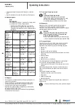
4.4 Connection diagram

No.

Conn.

Designation

Function/assignment

CON1

L1, L2, L3

Power supply, phase, see nameplate for voltage range

PE

PE

Protective earth

CON2

RSA

RS485 interface for MODBUS, RSA; SELV

CON2

RSB

RS485 interface for MODBUS, RSB; SELV

CON2

GND

Reference ground for control interface, SELV

CON2

IO1

Function parameterizable (see “Optional interface functions” table)
Factory setting:
Digital input - high active, function: Disable input, SELV
- inactive: Pin open or applied voltage < 1.5 VDC
- active: applied voltage 3.5-50 VDC
Reset function: Triggering of error reset on change of state from "enabled" to "disabled"

CON2

IO2

Function parameterizable (see “Optional interface functions” table)
Factory setting:
Analog input 0-10 V/PWM, Ri=100 kΩ, function: Set value
Characteristic curve parameterizable (see input characteristic curve P1-IN), SELV

CON2

IO3

Function parameterizable (see “Optional interface functions” table)
Factory setting:
Analog output 0-10 V, max. 5 mA, function: Actual speed
Characteristic curve parametrizable (see output characteristic curve P3-OUT), SELV

CON2

Vout

Voltage output 3.3-24 VDC ±5%, Pmax=800 mW, voltage parameterizable
Factory setting: 10 VDC
short-circuit-proof, supply for external devices, SELV
alternatively: 15-50 VDC input for parameterization via MODBUS without line voltage

CON2

COM

Status relay, floating status contact, common connection, contact rating 250 VAC / 2 A (AC1) / min. 10 mA,
reinforced insulation on supply side and on control interface side

CON2

NC

Status relay, floating status contact, break for failure

LED

green: status = good, ready for operation
orange: status = warning
red: status = failure

P1-IN

Input characteristic curve

P3-OUT

Output characteristic curve

Item no. 1170000663 · ENU · Change 262664 · Approved 2022-10-26 · Page 11 / 17

ebm-papst Mulfingen GmbH & Co. KG · Bachmühle 2 · D-74673 Mulfingen · Phone +49 (0) 7938 81-0 · Fax +49 (0) 7938 81-110 · info1@de.ebmpapst.com · www.ebmpapst.com

Summary of Contents for VBS0450CTTPS

Page 1: ...re permitted to install the device to carry out a test run and to perform work on the electrical installation 1 3 Basic safety rules 1 1 3 Basic safety rules The safety hazards associated with the dev...

Page 2: ...levels occur following installation appropriate shielding measures have to be taken by the user NOTE Electrical or electromagnetic interference after installing the device in customer equipment Verif...

Page 3: ...nly in stationary systems Performing all maintenance work Conveying air at an ambient air pressure between 800 mbar and 1050 mbar Using the device within the permitted ambient temperature range see Ch...

Page 4: ...Cable diameter min 4 mm max 10 mm tightening torque 4 0 6 Nm 4 Cable diameter min 5 mm max 14 mm tightening torque 6 0 9 Nm The tightening torque is designed for PVC cables If the cable materials are...

Page 5: ...k factor 232 1 Fastening holes for FlowGrid 35505 2 2957 not included in scope of delivery are provided and must be subsequently opened as required Item no 1170000663 ENU Change 262664 Approved 2022...

Page 6: ...sions must be requested from ebm papst If other air conduction geometries are used on the installation side the ebm papst evaluation loses its validity the conformity must be confirmed again The produ...

Page 7: ...responsibility of the installation engineer or operator owner of the device to ensure if necessary after consultation with the network operator that this device is only connected to a connection poin...

Page 8: ...rotection Nominal voltage Fuse Automatic circuit breaker Cable cross section Cable cross section VDE UL VDE mm AWG 3 PE AC 380 480 VAC 20 A 20 A C20A 2 5 14 3 PE AC 380 480 VAC 25 A 25 A C25A 4 0 12 3...

Page 9: ...re end ferrules For flexible control and relay cables from a cable cross section of 1 0 mm a trapezoid crimp is required to ensure correct installation on the connector Fig 2 Trapezoid crimp 4 3 3 Con...

Page 10: ...awing 4 3 4 Cable routing Water must be prevented from reaching the cable gland along the cable NOTE Damage caused by moisture penetration Moisture can penetrate into the terminal box if water is cons...

Page 11: ...ut characteristic curve P1 IN SELV CON2 IO3 Function parameterizable see Optional interface functions table Factory setting Analog output 0 10 V max 5 mA function Actual speed Characteristic curve par...

Page 12: ...SELV D159 0 Ain2 0 10V PWM analog input D159 2 Ri 100K characteristic curve parameterizable f PWM 1k 10KHz SELV Ain2 4 20mA analog input Ri 125R characteristic curve parameterizable SELV D159 3 Din3 a...

Page 13: ...inal operating instructions 4 6 Equivalent circuit diagrams Item no 1170000663 ENU Change 262664 Approved 2022 10 26 Page 13 17 ebm papst Mulfingen GmbH Co KG Bachm hle 2 D 74673 Mulfingen Phone 49 0...

Page 14: ...Switching off the device Switching off the device during operation Switch off the device via the control input Do not switch the motor e g in cyclic operation on and off via power supply Switching of...

Page 15: ...upply Attention The error message resets automatically Device restarts automatically without warning Faulty connection Isolate from supply correct connection see connection diagram Broken motor windin...

Page 16: ...ening diameter on the motor support plate in the direction of the motor axis of rotation and perpendicular to this Fig 5 Example illustrating vibration measurement The arrangement of the sensors depen...

Page 17: ...dations for ecological disposal of the product and its components 6 5 1 Country specific legal requirements NOTE Country specific legal requirements Always observe the applicable country specific lega...

Reviews: