Operating instructions
8300100076
VBS0450CTTPS
Translation of the original operating instructions
6.1.2 Status codes
Manual reset by "Switch off line voltage - wait briefly - switch line
voltage back on" or, if provided,
via the "Fan enable/disable" input
Number of
pulses
Motor status -
LED red
Possible cause Possible
remedy
1
Phase failure or
line undervoltage
Missing phase
Poor power
supply quality
Check line
voltage
3
Output stage
overheating
Electronics
housing
contaminated
Provide better
cooling.
Manual reset
required
4
Communication
error between
master
controller and
slave controller
External
supply applied
via Vout for
setting
parameters.
Internal error
Switch off line
voltage
- wait -
switch back on
6
Motor
overheating
Ambient
temperature too
high
Impermissible
operating point
Reduce
ambient
temperature
Correct
operating point.
Manual reset
required
7
Hall sensor error Internal error
Switch off line
voltage
- wait -
switch back on
8
Motor blocked
Mechanical
blockage
Switch off
- check safe
isolation from
supply -
check
freedom of
movement of
rotor
9
Speed limit
exceeded
-
-
11
Rotor position
sensor
calibration error
Observe
ebm-papst
replacement
instructions
Rotor position
sensor
calibration
necessary.
Notify ebm-
papst
13
DC-link
undervoltage
Line voltage not
OK
Check the line
voltage applied.
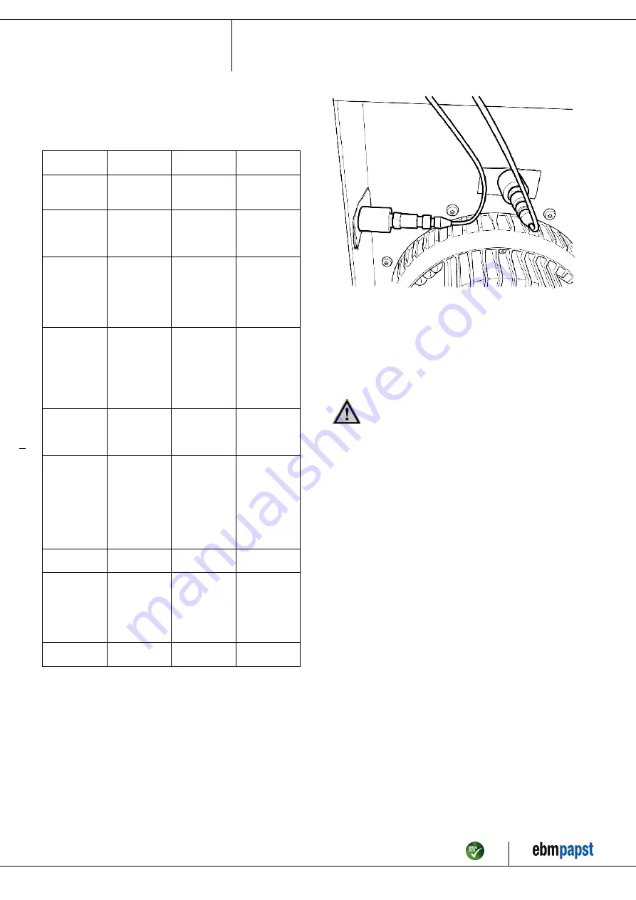
6.2 Vibration testing
If the vibration sensor integrated in the fan’s motor is not to be used, the
following “manual” vibration test must be performed. This vibration test
must be performed for each fan separately and across the fan’s entire
speed range. Speed ranges with excessive vibration speeds are to be
avoided in continuous operation. The vibration test must be performed
every 6 months.
Checking of fan for mechanical vibration based on ISO 14694.
Recommendation: Every 6 months. Max. vibration severity is 3.5 mm/
s, measured at the motor fastening diameter on the motor support plate in
the direction of the motor axis of rotation and perpendicular to this.
Fig. 5: Example illustrating vibration measurement. The arrangement of
the sensors depends on the device concerned and the installation
situation.
6.3 Cleaning
To ensure a long service life, check the fans regularly for proper
operation and soiling. The frequency of checking is to be adapted
accordingly depending on the degree of soiling.
DANGER
Risk of injury from rotating fan.
→ Only clean when not in motion. Do not disconnect the fan
from the power supply, just switch it off via the control input.
This will prevent start-up of the fan.
;
Dirt deposits on the motor housing can cause overheating of the motor.
;
Soiling of the impeller can cause vibration that will shorten the service
life of the fan.
;
Severe vibration can destroy the fan.
;
In such cases, switch off the fan immediately and clean it.
;
The preferred method of cleaning is dry cleaning, e.g. using
compressed air.
;
Do not use aggressive cleaning agents!
NOTE
Damage to the device during cleaning
Malfunction possible
→ Do not clean the device using a high-pressure cleaner.# Do
not use acid, alkali or solvent-based cleaning agents.
→ Do not use any pointed or sharp-edged objects for
cleaning.
;
Completely remove any cleaning agents used.
;
If severe corrosion is visible on load-bearing or rotating parts, switch
off the device immediately and replace it.
;
Repair of load-bearing or rotating parts is not permitted!
;
Operate the fan for 2 hours at maximum speed so that any water that
has ingressed can evaporate.
;
If cleaning does not eliminate vibrations, the fan may need to be
rebalanced. To have it rebalanced, contact ebm-papst.
;
The fan is equipped with maintenance-free ball bearings. The lifetime
lubrication of the ball bearings is designed for a service life of 40,000
hours.
Item no. 1170000663 · ENU · Change 262664 · Approved 2022-10-26 · Page 16 / 17
ebm-papst Mulfingen GmbH & Co. KG · Bachmühle 2 · D-74673 Mulfingen · Phone +49 (0) 7938 81-0 · Fax +49 (0) 7938 81-110 · info1@de.ebmpapst.com · www.ebmpapst.com