background image

Operating instructions

W2D250-CH02-01

Translation of the original operating instructions

CAUTION
Voltage

The fan is a built-in component and has no disconnecting switch.
→ Only connect the fan to circuits that can be switched off with

an all-pole disconnection switch.

→ When working on the fan, secure the system/machine in

which the fan is installed so as to prevent it from being
switched back on.

NOTE
Water ingress into wires or cables

Water ingress at the customer end of the cable can damage the
device.
→ Make sure the end of the cable is connected in a dry

environment.

Only connect the device to circuits that can be switched off with
an all-pole disconnection switch.

4.2.1 Requirements

;

Check whether the data on the nameplate match the connection data.

;

Before connecting the device, make sure the power supply matches
the device voltage.

;

Only use cables designed for the current level indicated on the
nameplate.
For determining the cross-section, note the sizing criteria according
to EN 61800-5-1. The protective earth must have a cross-section
equal to or greater than that of the phase conductor.
We recommend the use of 105 °C cables. Ensure that the minimum
cable cross-section is at least
AWG 26 / 0.13 mm².

Ground conductor contact resistance according to EN 60335

Compliance with the impedance specifications according to EN 60335
for the protective earth connection circuit must be verified in the end
application.
Depending on the circumstances of installation, it may be necessary to
connect an additional protective earth conductor to the extra protective
earth terminal on the device.

4.2.2 Voltage control

With speed control using transformers or electronic voltage
regulators (e.g. phase control), excessive current may occur.
In addition, depending on how the device is installed, noises
can occur with phase control.

4.2.3 Variable frequency drive

Please use a variable frequency drive only after consultation with ebm-
papst.

For operation with variable frequency drives, install sinusoidal
filters that work on all poles (phase-phase and phase-ground)
between the drive and the motor.
During operation with variable frequency drives, an all-pole
sine filter protects the motor against high-voltage transients that
can destroy the coil insulation system, and against harmful
bearing currents.

Heating of the motor due to use of a variable frequency drive must be
checked in the application by the customer.

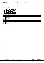
4.3 Connecting the cables

The device has external leads.

;

First connect the "PE" (protective earth).

Connect the cables according to your application. When doing so,
observe Chapter 4.4 Connection diagram.
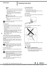
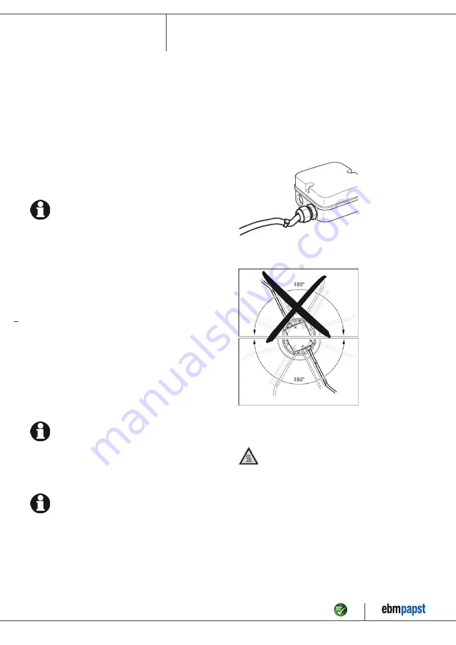
4.3.1 Cable routing

Water must be prevented from reaching the cable exit along the cable.

Fans installed lying flat

Fig. 1: Fan installed lying flat, cable routed in a U-shaped loop.

Fans installed upright

Fig. 2: Cable routing for fans installed upright. The cables must always
be routed downward.

4.3.2 Motor protection

WARNING
Device has no overheating protection

The device is supplied without any automatic overheating
protection. The device can become hot and catch fire.
→ For the version without thermal overload protector, also

install a suitable motor protection switch.

Item no. 10225-5-9970 · ENU · Change 89188 · Approved 2016-04-18 · Page 6 / 9

ebm-papst Mulfingen GmbH & Co. KG · Bachmühle 2 · D-74673 Mulfingen · Phone +49 (0) 7938 81-0 · Fax +49 (0) 7938 81-110 · info1@de.ebmpapst.com · www.ebmpapst.com

Summary of Contents for W2D250-CH02-01

Page 1: ...y only be transported unpacked installed operated maintained and otherwise used by suitably qualified trained and authorized technical staff Only authorized specialists are permitted to install the device to carry out a test run and to perform work on the electrical installation 1 3 Basic safety rules 1 1 3 Basic safety rules The safety hazards associated with the device must be assessed again fol...

Page 2: ... contact Before working on the system machine wait until all parts have come to a standstill WARNING Rotating device Long hair and dangling items of clothing jewelry and the like can become entangled and be pulled into the device Injuries can result Do not wear any loose fitting or dangling clothing or jewelry while working on rotating parts Protect long hair with a cap 1 7 Emissions WARNING Depen...

Page 3: ...ata Operating the device with all protective devices Following the operating instructions Improper use In particular operating the device in the following ways is prohibited and could be hazardous Operating the device in an unbalanced state e g due to dirt deposits or ice formation Conveying air that contains abrasive particles Conveying highly corrosive air e g salt spray Exception devices design...

Page 4: ...ions in mm 1 Cable PVC 7x crimped splices 2 Direction of air flow V 3 Direction of rotation counterclockwise viewed toward rotor Item no 10225 5 9970 ENU Change 89188 Approved 2016 04 18 Page 4 9 ebm papst Mulfingen GmbH Co KG Bachmühle 2 D 74673 Mulfingen Phone 49 0 7938 81 0 Fax 49 0 7938 81 110 info1 de ebmpapst com www ebmpapst com ...

Page 5: ...or a maximum of one million load cycles If you have special questions consult ebm papst for support 3 4 Mounting data For screw clearance see Chapter 3 1 Product drawing Secure the screws against unintentional loosening e g use self locking screws Any further mounting data required can be taken from the product drawing 3 5 Transport and storage conditions Use the device in accordance with its degr...

Page 6: ...e 4 2 2 Voltage control With speed control using transformers or electronic voltage regulators e g phase control excessive current may occur In addition depending on how the device is installed noises can occur with phase control 4 2 3 Variable frequency drive Please use a variable frequency drive only after consultation with ebm papst For operation with variable frequency drives install sinusoida...

Page 7: ... two phases Three phase motor Δ Delta connection Y Star connection L1 U1 black L2 V1 blue L3 W1 brown U2 green V2 white W2 yellow PE green yellow Item no 10225 5 9970 ENU Change 89188 Approved 2016 04 18 Page 7 9 ebm papst Mulfingen GmbH Co KG Bachmühle 2 D 74673 Mulfingen Phone 49 0 7938 81 0 Fax 49 0 7938 81 110 info1 de ebmpapst com www ebmpapst com ...

Page 8: ...tor restarts automatically when operating voltage is applied e g after a power failure Risk of injury Keep out of the device s danger zone When working on the device switch off the line voltage and ensure that it cannot be switched back on Wait until the device comes to a stop If the device is out of use for some time e g when in storage we recommend switching it on for at least two hours to allow...

Page 9: ...so to be heeded 5 3 2 Disassembly Disassembly of the product must be performed or supervised by qualified personnel with the appropriate technical knowledge The product is to be disassembled into suitable components for disposal employing standard procedures for motors WARNING Heavy parts of the product may drop off Some of the product components are heavy These components could drop off during di...

Reviews: