


Operating instructions
W2E250-HP06-01
Translation of the original operating instructions
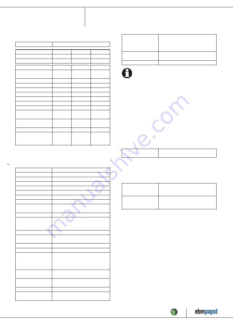
3.2 Nominal data
Motor
M2E068-CF
Phase
1~
1~
1~
Nominal voltage / VAC
230
230
230
Frequency / Hz
50
60
60
Type of data definition
ml
ml
ml
Valid for approval /
standard
CE
CE
UL 2111
Speed (rpm) / min
-1
2320
2300
2300
Power input / W
125
160
166
Current draw / A
0.55
0.71
0.74
Motor capacitor / µF
3
3
3
Capacitor voltage / VDB
400
400
400
Capacitor standard
S0 (CE)
S0 (CE)
S0 (CE)
Max. back pressure / Pa
100
110
110
Min. ambient
temperature / °C
-25
-25
-25
Max. ambient
temperature / °C
60
50
50
Starting current / A
0.83
0.81
0.81
Max. safe operating
speed (rpm) /
min
-1
3000
@ 60 °C
3000
@ 60 °C
3000
@ 60 °C
ml = Max. load · me = Max. efficiency · fa = Running at free air
cs = Customer specs · cu = Customer unit
Subject to alterations
3.3 Technical features
Mass
2.7 kg
Size
250 mm
Surface of rotor
Coated in black
Material of blades
PP plastic
Housing material
Die-cast aluminium
Number of blades
7
Direction of air flow
"V"
Direction of rotation
Counter-clockwise, seen on rotor
Type of protection
IP 44; Depending on installation and
position
Insulation class
"F"
Humidity (F)/
environmental
protection class (H)
H0 - dry environment
Mounting position
Any
Condensate discharge
holes
None
Operation mode
S1
Motor bearing
Ball bearing
Touch current acc.
IEC 60990 (measuring
network Fig. 4, TN
system)
< 0.75 mA
Electrical leads
Via terminal strips, integrated capacitor
connected via terminal strips
Motor protection
Thermal overload protector (TOP) wired
internally
Cable exit
Variable
Protection class
I (if protective earth is connected by
customer)
Motor capacitor
according to EN 60252-
1 in safety protection
class
S0
Product conforming
to standard
EN 60335-1; CE
Approval
UL 2111; CSA C22.2 No.77; EAC; CCC
For cyclic speed loads, note that the rotating parts of the device
are designed for maximum one million load cycles. If you have
specific questions, contact ebm-papst for support.
The surfaces of the products conform to the generally applicable industrial
standard. The surface quality may vary during the production period.
Strength, dimensional stability and dimensional accuracy are not affected
by this.
The colour pigments of the paints used react perceptibly to UV light over
the course of time. This does not however have any influence on the
technical properties of the products. To prevent the formation of patches
and fading, the product is to be protected against UV radiation. Changes
in colour are not a reason for complaint and are not covered by the
warranty.
3.4 Mounting data
For depth of screw, see chapter 3.1 Product drawing
;
Secure the mounting screws against accidentally coming loose (e.g.
by using self-locking screws).
Strength class for
mounting screws
8.8
You can obtain additional mounting data from the product drawing if
necessary.
3.5 Transport and storage conditions
;
Use the device in accordance with its protection type.
Max. permissible
ambient motor temp.
(transp./ storage)
+ 80 °C
Min. permissible
ambient motor temp.
(transp./storage)
- 40 °C
Item no. 14228-5-9970 · ENG · Revision 88948 · Release 2016-08-26 · Page 5 / 10
ebm-papst Mulfingen GmbH & Co. KG · Bachmühle 2 · D-74673 Mulfingen · Phone +49 (0) 7938 81-0 · Fax +49 (0) 7938 81-110 · info1@de.ebmpapst.com · www.ebmpapst.com


